Stack Mold Design Guide: Structure, Cooling, and Automation

Stack mold design increases production output by arranging two or more cavity levels around a central mold section. Compared with a conventional single-face mold, a stack mold can produce more parts during each cycle without requiring a proportional increase in machine platen area.

This makes stack molds attractive for high-volume products such as packaging components, caps, medical consumables, thin-wall parts, and other applications with sustained production demand.

However, adding another molding level also increases structural, thermal, flow, ejection, and automation complexity. A stack mold is not simply a conventional mold with more cavities. It is a coordinated mechanical system in which small imbalances can be amplified across multiple cavity levels.

Successful stack mold design depends on balanced load transfer, runner symmetry, cooling uniformity, reliable opening sequences, machine compatibility, automation stability, and long-term maintenance access.


What Is Stack Mold Design?

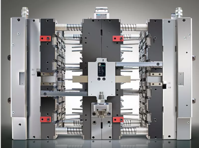
stack mold design for multi-level high-volume injection molding
High-cavity stack mold with multiple layers and middle plate for high-throughput injection molding

A stack mold contains multiple cavity faces arranged in layers. The most common two-level configuration includes:

  • A stationary mold section
  • A central section with cavity faces on both sides
  • A moving mold section
  • Two parting lines
  • A synchronized opening system
  • A runner or hot-runner system supplying all cavity levels

When the mold opens, both cavity levels release parts during the same cycle.

For example, if a conventional mold contains eight cavities, a two-level stack mold may produce sixteen parts per cycle while using a similar projected platen area. Actual machine requirements still depend on projected area, injection pressure, mold weight, daylight, shot size, and opening stroke.

The objective of stack mold design is not simply to maximize cavity count. It is to increase output while maintaining repeatable filling, cooling, ejection, and part quality across every cavity.


When Does a Stack Mold Make Sense?

Before selecting this tooling structure, manufacturers should first evaluate whether a stack mold is suitable for the expected production volume, part geometry, and equipment conditions.

Stack molds are most suitable when:

  • Production demand is consistently high
  • The product design is stable
  • Annual volume justifies higher tooling investment
  • Machine platen area is a limiting factor
  • Part geometry supports balanced cavity arrangement
  • Automation can handle simultaneous part release
  • Material and process conditions are well understood
  • Long-term production planning is available

A stack mold may be unsuitable when:

  • Product demand is uncertain
  • Design changes are still likely
  • Production volumes are low
  • The selected machine lacks sufficient daylight or shot capacity
  • Maintenance resources are limited
  • The part requires complex side actions on every level
  • Gate vestige or automation requirements cannot be controlled reliably

The economic benefit depends on total lifecycle output, not only initial cycle-time calculations.


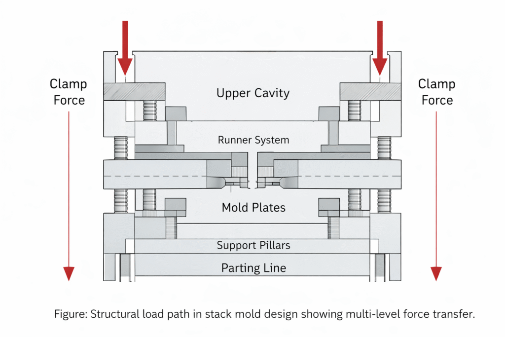
1. Structural Load Path and Clamp Force Distribution

stack mold design structural load path and clamp force distribution

During injection, cavity pressure creates forces that must be transferred through the mold and contained by the machine.

Autodesk explains that required clamp force is determined by integrating cavity pressure across the projected area, which is an important consideration when validating multi-level mold structures.

In a stack mold, these loads pass through:

  • Multiple cavity plates
  • The central mold section
  • Support pillars
  • Guide components
  • Parting lines
  • Machine platens

If structural load paths are not symmetrical, the central section may deflect or tilt under pressure.

Possible consequences include:

  • Flash on one cavity level
  • Uneven parting-line contact
  • Insert movement
  • Premature guide-component wear
  • Cavity-to-cavity dimensional variation
  • Sealing problems
  • Long-term fatigue

The mold structure should distribute clamp force evenly across all cavity levels. Support locations, plate thickness, steel selection, and cavity arrangement must be evaluated under realistic injection pressure rather than only static mold weight.


2. Central Section Rigidity and Deflection Control

stack mold design showing central section rigidity and multi-level structure

The central section is one of the most critical components in a stack mold. It contains cavity surfaces on both sides and may also support the hot-runner system, cooling circuits, guide mechanisms, and opening components.

Insufficient rigidity can cause:

  • Central plate bending
  • Parting-line mismatch
  • Uneven cavity compression
  • Flash
  • Seal damage
  • Hot-runner alignment problems
  • Accelerated wear

Increasing plate thickness alone does not always solve the problem. Rigidity also depends on:

  • Cavity placement
  • Support geometry
  • Internal channel routing
  • Hot-runner clearances
  • Steel properties
  • Opening-system loads
  • Thermal expansion

Structural analysis should consider both injection pressure and repeated thermal cycling.


3. Runner Balance Across Cavity Levels

All cavities must receive molten material under comparable pressure and temperature conditions.

In a stack mold, the runner system must distribute material across:

  • Different cavity levels
  • Multiple flow branches
  • Extended hot-runner paths
  • High cavity counts

A geometrically balanced runner does not always provide true rheological balance. Melt temperature, shear history, pressure loss, gate dimensions, and cavity cooling conditions also affect filling.

Poor runner balance may cause:

  • Early filling in some cavities
  • Short shots in distant cavities
  • Uneven packing
  • Part-weight variation
  • Different shrinkage behavior
  • Cavity-specific dimensions
  • Inconsistent surface appearance

Runner balance should be evaluated using realistic material data and processing conditions. Cavity pressure and part-weight measurements should then confirm the design during validation.


4. The Compounding Effect of High Cavity Counts

High cavity counts increase production capacity, but they also make the process more sensitive to small deviations.

A minor variation in one gate, cavity, cooling circuit, or vent may have little impact in a low-cavity mold. In a high-cavity stack mold, similar variations may occur across several locations and create a larger overall yield loss.

Increasing cavity count affects:

  • Runner pressure loss
  • Shot-size consistency
  • Cooling-flow demand
  • Venting capacity
  • Ejection synchronization
  • Sensor requirements
  • Inspection workload
  • Scrap management

The mold should not be considered successful merely because all cavities fill. It must produce consistent parts across every cavity and both stack levels over long production runs.


5. Gate Design and Gate Balance

Gate type, size, and location affect how each cavity fills and packs.

Inconsistent gates can create:

  • Different filling times
  • Uneven gate freeze-off
  • Part-weight variation
  • Gate blush
  • Stringing
  • Gate vestige differences
  • Localized shear
  • Dimensional variation

For hot-runner stack molds, thermal consistency at each nozzle and gate is essential. Small temperature differences may change viscosity and create cavity imbalance.

Valve-gate systems can provide additional control but introduce greater complexity in timing, actuation, maintenance, and failure diagnosis.

Gate validation should compare cavity pressure, part weight, gate appearance, dimensions, and filling behavior across every cavity.


6. Thermal Uniformity Across Multiple Levels

Stack molds contain more steel, cavities, runner components, and thermal interfaces than conventional molds.

Potential sources of thermal imbalance include:

  • Different cooling-channel distances
  • Unequal coolant-flow rates
  • Longer circuits on one level
  • Heat from the hot-runner manifold
  • Limited cooling space in the central section
  • Different insert structures
  • Uneven coolant inlet temperatures
  • Restricted channels

Thermal imbalance may cause:

  • Different cooling times between levels
  • Warpage variation
  • Inconsistent shrinkage
  • Ejection differences
  • Cycle-time limitations
  • Dimensional drift

Cooling design should be balanced between cavity levels and validated after the mold reaches stable operating temperature.


7. Cooling the Middle Plate

The middle plate presents a particular cooling challenge because it contains molding surfaces on both sides while often housing runner and mechanical components internally.

Poor cooling in this section may create:

  • Heat accumulation
  • Longer cycle times
  • Central-plate thermal expansion
  • Different temperatures between cavity faces
  • Hot-runner instability
  • Uneven part shrinkage

Cooling channels must be arranged without weakening the structure or interfering with the hot-runner system.

Depending on geometry, possible solutions include:

  • Independent cooling circuits
  • Baffles
  • Bubblers
  • High-conductivity inserts
  • Thermal pins
  • Conformal cooling
  • Additional temperature sensors

Each solution should be evaluated for performance, manufacturability, cleaning, and long-term maintenance.


8. Machine Compatibility

A stack mold must be matched to the molding machine as a complete system.

Important machine requirements include:

  • Platen dimensions
  • Tie-bar spacing
  • Mold weight capacity
  • Maximum daylight
  • Opening stroke
  • Ejector stroke
  • Shot capacity
  • Plasticizing capacity
  • Injection pressure
  • Clamp force
  • Hot-runner control capacity
  • Hydraulic or pneumatic connections
  • Automation access

A mold may fit between the tie bars but still be unsuitable because the machine lacks sufficient daylight, shot capacity, or support for the mold weight.

The increased mold depth can also change robot access and part-removal timing.

Machine compatibility should be confirmed before detailed tool construction begins.


9. Opening Sequence and Synchronization

Stack molds normally require both parting lines to open in a controlled sequence.

The opening system may use:

  • Mechanical linkages
  • Rack-and-pinion systems
  • Hydraulic cylinders
  • Timing bars
  • Gear mechanisms
  • Other synchronized systems

If opening is not synchronized:

  • One level may release too early
  • Parts may remain trapped
  • Ejection timing may become inconsistent
  • The middle section may tilt
  • Guide components may wear unevenly
  • Robots may miss parts

Opening forces, stroke length, speed, alignment, and long-term wear should be considered during design.

The system must remain synchronized after repeated cycling, not only during initial mold trials.


10. Ejection System Stability

Every cavity must release its part consistently.

Ejection variation may result from:

  • Uneven cooling
  • Different shrinkage between levels
  • Inconsistent draft
  • Imbalanced ejector layouts
  • Varying surface conditions
  • Misaligned opening sequences
  • Ejector wear

A single retained part can stop the complete production cell.

Ejection design should consider:

  • Ejector-force distribution
  • Part support during release
  • Ejector-pin location
  • Stripper systems
  • Air assist
  • Surface finish
  • Draft angle
  • Return confirmation
  • Part-presence detection

The ejection system should be validated at the intended production cycle time and mold temperature.


11. Automation for High-Cavity Stack Molds

High-output stack molds often depend on automation for part removal, separation, inspection, and packaging.

Automation must handle:

  • Parts released from multiple levels
  • Short opening windows
  • High part counts per cycle
  • Limited space between mold sections
  • Different part orientations
  • Runner or gate separation
  • Cavity-specific traceability
  • Rejected-part handling

The mold, machine, robot, conveyor, and inspection systems should be designed as one production cell.

Automation added after the mold is completed may encounter:

  • Insufficient access
  • Inadequate opening stroke
  • Part collisions
  • Unstable grip points
  • Excessive removal time
  • Incomplete part detection

Early coordination reduces these risks.


12. Part Handling and Removal

Parts may fall freely, be removed by robots, or be transferred using specialized end-of-arm tooling.

The selected method depends on:

  • Part size
  • Surface requirements
  • Material stiffness
  • Part orientation
  • Gate type
  • Cycle time
  • Cleanliness requirements
  • Risk of deformation

Free-drop removal may be unsuitable for cosmetic or easily damaged parts. Robotic removal offers more control but increases cycle coordination and equipment complexity.

Part-removal validation should confirm that every cavity releases correctly without:

  • Scratching
  • Deformation
  • Mixing accepted and rejected parts
  • Leaving parts inside the mold
  • Extending cycle time excessively

13. Scrap Management

High-cavity stack molds produce many parts during each cycle. One abnormal cavity can therefore generate a significant quantity of scrap before the problem is detected.

A production system should be able to:

  • Identify the affected cavity
  • Separate rejected parts
  • Detect incomplete shots
  • Confirm successful part removal
  • Track cavity-specific defects
  • Stop production when necessary

Simply mixing every part into one container makes root-cause analysis more difficult.

Cavity identification, vision inspection, weight monitoring, sensors, or automated sorting may be required depending on product risk.


14. In-Line Quality Monitoring

Manual inspection alone may not be sufficient for high-output production.

Useful monitoring methods include:

  • Cavity-pressure sensors
  • Mold-temperature sensors
  • Part-presence sensors
  • Vision inspection
  • Part-weight sampling
  • Dimensional sampling
  • Cycle-time monitoring
  • Hot-runner temperature alarms
  • Coolant-flow monitoring

The objective is not to collect data without purpose. Monitoring should detect changes early enough to prevent large quantities of nonconforming parts.

Alarm limits should be based on validated process behavior rather than arbitrary settings.


15. Venting in High-Cavity Stack Molds

Each cavity must release displaced air during filling.

Inadequate venting may cause:

  • Burn marks
  • Short shots
  • Surface defects
  • High injection pressure
  • Uneven filling
  • Material degradation

High cavity counts increase the number of venting locations that require inspection and maintenance.

Vents may gradually become blocked by deposits, especially during long production runs. Vent accessibility and cleaning procedures should be included in preventive maintenance planning.


16. Middle Parting-Line Sealing

The middle parting lines must maintain stable contact under repeated injection pressure and thermal cycling.

Poor sealing may cause:

  • Flash
  • Resin leakage
  • Uneven cavity pressure
  • Surface damage
  • Increased cleaning requirements
  • Safety risks

Sealing stability depends on:

  • Structural rigidity
  • Plate flatness
  • Clamp-force distribution
  • Alignment
  • Thermal expansion
  • Wear condition
  • Surface maintenance

Repeated flash should not be treated only as a process-parameter problem. It may indicate structural or alignment issues within the stack mold.


17. Maintenance Accessibility

Stack molds contain more components and more internal interfaces than conventional molds.

Maintenance teams may need access to:

  • Hot-runner components
  • Cooling connections
  • Valve-gate systems
  • Opening mechanisms
  • Guide components
  • Ejection systems
  • Middle-plate inserts
  • Sensors
  • Seals
  • Vents

If critical components cannot be inspected or replaced without extensive mold disassembly, downtime and repair costs increase.

Design should include:

  • Replaceable wear components
  • Clearly identified cooling circuits
  • Accessible connectors
  • Documented assembly sequences
  • Spare-part planning
  • Defined inspection intervals

Maintenance accessibility is part of production design, not an issue to address after failure.


18. Long-Term Wear and Production Drift

Stack molds experience repeated mechanical and thermal loading across multiple levels.

Understanding the underlying mold wear mechanisms helps maintenance teams identify structural fatigue, thermal damage, and progressive clearance changes before production becomes unstable.

Over time, small changes may appear in:

  • Gate dimensions
  • Guide clearances
  • Parting-line contact
  • Cooling-flow rates
  • Ejector movement
  • Opening synchronization
  • Hot-runner performance

These changes can gradually narrow the process window and create production drift.

Preventive monitoring should compare:

  • Cavity-to-cavity part weight
  • Dimensional trends
  • Cycle-time trends
  • Injection-pressure curves
  • Cooling-flow data
  • Mold-temperature data
  • Maintenance history
  • Scrap distribution

Trend analysis can reveal deterioration before a complete mold failure occurs.


19. Stack Mold Validation Before Mass Production

Validation should confirm more than successful filling.

The difference between controlled mold trials and continuous production should also be considered when defining the validation plan.

A complete evaluation should include:

Filling and Packing

  • All cavities fill consistently
  • Cavity-pressure profiles are comparable
  • Part-weight variation is controlled
  • Gates freeze within the intended process window
  • No cavity depends on excessive pressure

Thermal Performance

  • Cooling flow is measured
  • Temperature differences between levels are acceptable
  • The middle section does not accumulate excessive heat
  • Warpage remains consistent
  • Target cycle time is thermally sustainable

Mechanical Performance

  • Both parting lines open synchronously
  • The middle section remains aligned
  • Ejection is stable
  • No abnormal wear appears
  • Clamp-force distribution is appropriate

Automation

  • Every part is removed successfully
  • Part-presence sensors function correctly
  • Rejected parts can be separated
  • Robot movement does not extend cycle time unnecessarily
  • Recovery procedures are defined

Continuous Production

  • The mold runs for a sustained period
  • Dimensions remain stable after thermal equilibrium
  • Scrap does not increase over time
  • Process parameters remain within validated limits
  • Maintenance requirements are documented

Stack Mold Design Checklist

Before approving a stack mold, review the following.

Product and Volume

  • Is demand high and stable enough to justify the tooling?
  • Is the product design mature?
  • Are annual volume and lifecycle requirements defined?
  • Are quality and cosmetic standards clear?

Mold Structure

  • Are load paths symmetrical?
  • Is the middle section sufficiently rigid?
  • Are support locations optimized?
  • Is deflection evaluated?
  • Are parting lines adequately sealed?

Flow System

  • Is the runner system rheologically balanced?
  • Are gate dimensions consistent?
  • Is hot-runner temperature control adequate?
  • Can cavity pressure be monitored?
  • Are material shear and pressure loss acceptable?

Cooling

  • Are both cavity levels thermally balanced?
  • Is the middle plate cooled effectively?
  • Are circuit lengths and flow resistance controlled?
  • Can every circuit be measured and cleaned?
  • Are hot spots identified?

Machine and Automation

  • Does the machine have sufficient daylight and opening stroke?
  • Are shot and plasticizing capacities adequate?
  • Can the machine support the mold weight?
  • Is automation access sufficient?
  • Can all parts be removed and tracked reliably?

Maintenance

  • Are wear components replaceable?
  • Are cooling and hot-runner connections accessible?
  • Can the opening system be inspected?
  • Are spare parts planned?
  • Are preventive maintenance intervals documented?

Frequently Asked Questions

What is the main advantage of stack mold design?

The main advantage is increased output per cycle without a proportional increase in machine platen area. A two-level stack mold can potentially double the number of parts produced per cycle.

Does a stack mold require twice the clamp force?

Not automatically. Clamp-force requirements depend on projected area, cavity pressure, cavity arrangement, and mold design. Machine selection should be based on engineering calculations rather than cavity count alone.

Why are stack molds more difficult to balance?

Material must be distributed across multiple cavity levels and a larger number of cavities. Pressure loss, melt temperature, gate variation, and cooling differences can amplify imbalance.

What is the biggest risk in the middle plate?

The middle section must remain rigid, thermally stable, aligned, and adequately cooled while supporting cavities on both sides and often housing hot-runner components.

Are stack molds suitable for low-volume production?

Usually not. Higher design, manufacturing, automation, and maintenance costs normally require sustained production volume to justify the investment.

Can stack molds use conventional runners?

Some stack molds can use cold-runner arrangements, but many high-volume applications use hot-runner systems to reduce material waste and improve material delivery. The correct choice depends on the product and production requirements.

Why do stack mold problems sometimes appear only in mass production?

Short trials may not reveal thermal accumulation, opening-system wear, cooling restrictions, cavity imbalance, or automation instability. Continuous production exposes these long-term interactions.


Conclusion

Stack mold design can significantly increase injection molding output, but its success depends on far more than adding another cavity level.

Structural load paths, central-section rigidity, runner balance, gate consistency, cooling uniformity, machine compatibility, synchronized opening, ejection stability, automation, quality monitoring, and maintenance access must function as one coordinated system.

A stack mold should not be considered production-ready simply because every cavity fills during an early trial. It must demonstrate stable dimensions, balanced cavity performance, repeatable ejection, reliable automation, and sustainable cycle time after reaching thermal equilibrium.

When these factors are evaluated before tooling release and validated under realistic production conditions, stack molds can provide high output and long-term manufacturing efficiency without sacrificing process stability or product quality.

Get a Free Quote