
Vehicle-Mounted Electronics We Support
Different automotive electronic products may look simple from the outside, but connector position, mounting points, cable exits, and internal PCB clearance often decide whether the product can be assembled and installed smoothly.
Built for Automotive Requirements
Automotive production is not only about making parts. The key is whether the part can fit, connect, mount, and function reliably inside the vehicle.
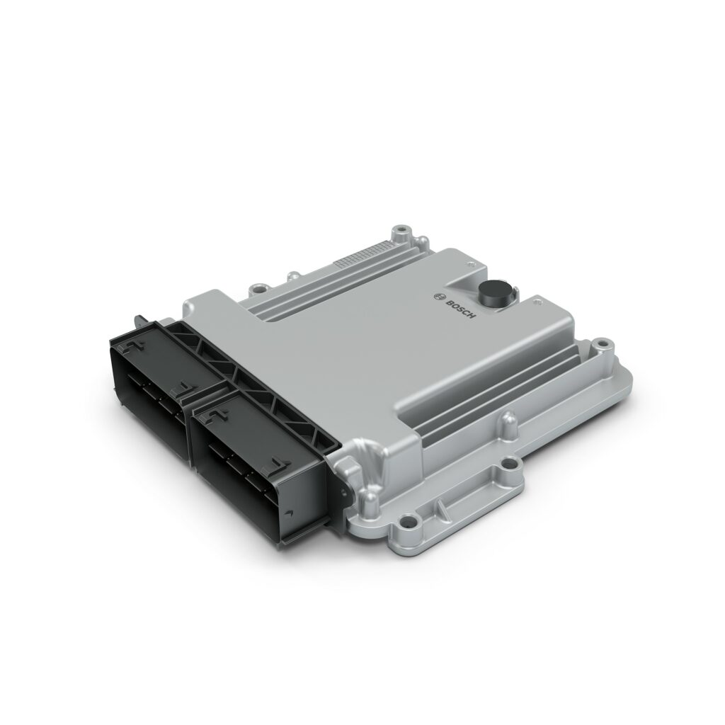
Vehicle Control
Module Housings
Focus on connector orientation, PCB fixing points, screw bosses, and enclosure strength for stable installation.
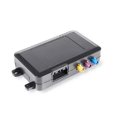
OBD & Telematics
Terminals
Support for compact housings where connector fit, internal PCB position, and plug-in stability need careful review.
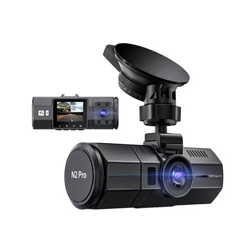
Driving Recorder
Enclosures
Attention to lens opening, bracket structure, heat dissipation space, and cable routing inside the housing.
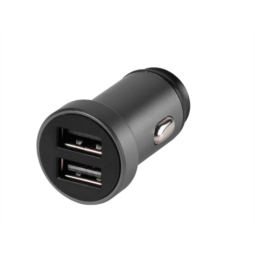
Car Charger
Modules
Review of port alignment, plastic housing fit, PCB clearance, and charging function checks before delivery.
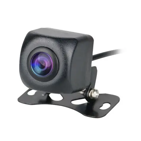
Rearview Camera
Modules
Support for small housings with lens position, sealing edges, cable exits, and assembly consistency.
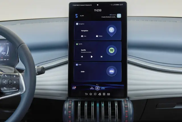
Navigation & Display
Components
Manufacturing support for display-related parts where front frame fit, internal fixing points, and cable space affect assembly.
Manufacturing Risks Behind Automotive Electronics
Automotive electronics may look compact, but many production issues come from hidden fit, routing, mounting, and heat-related details. Small oversights in these areas can lead to installation problems, field failures, and higher total costs.
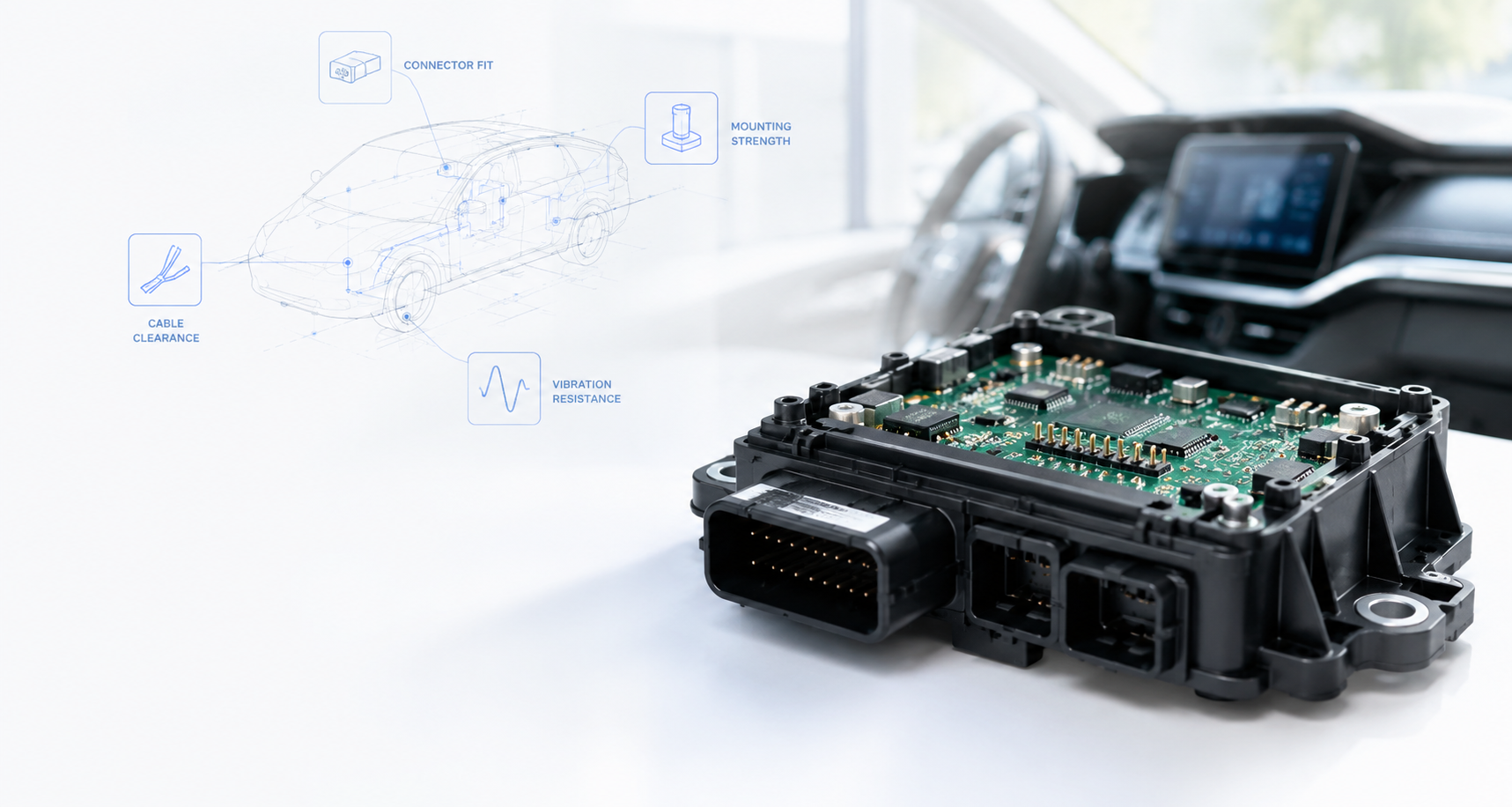
We focus on the details that affect assembly, reliability, and long-term performance in real vehicle conditions.
Connector Access & Fit
Reliable connection starts with proper connector design.
- Hard to plug in
- Loose or unstable connection
- Insufficient mating space
- Wrong direction or alignment
- Opening accuracy
- Connector direction
- Mating clearance
- Retention & locking design
Mounting Structure & Strength
Must withstand vibration and repeated installation.
- Screw boss cracking
- Clips or brackets break
- Loosening after vibration
- Poor load distribution
- Boss & clip strength
- Bracket position
- Wall thickness
- Vibration resistance
Cable Routing & Clearance
Proper routing avoids stress, interference, and damage.
- Cable bending or pinching
- Interference with parts
- Not enough exit space
- Pressure after enclosure close
- Cable exit position
- Internal path clearance
- Bend radius
- Space for movement
Heat Exposure & Environment
Heat and environment affect material and long-term stability.
- High temperature deformation
- Material aging
- Poor heat dissipation
- Condensation or sealing issues
- Material selection
- Heat source analysis
- Ventilation & spacing
- Sealing & environment
PCB & Housing Fit Tolerance
Accurate fit reduces assembly stress and functional issues.
- PCB position deviation
- Mismatch of holes or ports
- Assembly stress on PCB
- Function affected after install
- PCB position & support
- Hole & port alignment
- Enclosure dimensions
- Tight tolerance control
Quality Gate Control During Production
For vehicle-mounted electronics, production control is not limited to final inspection. Key details need to be checked at different stages, from molded housing fit to PCB placement, connector assembly, cable routing, and final functional verification.
Molded Housing Check
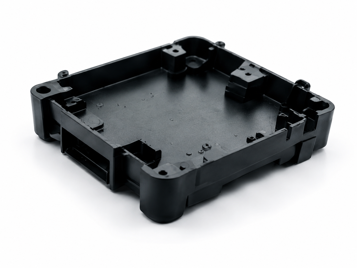
- Housing dimensions
- Connector openings
- Screw boss and clip areas
PCB Placement Check
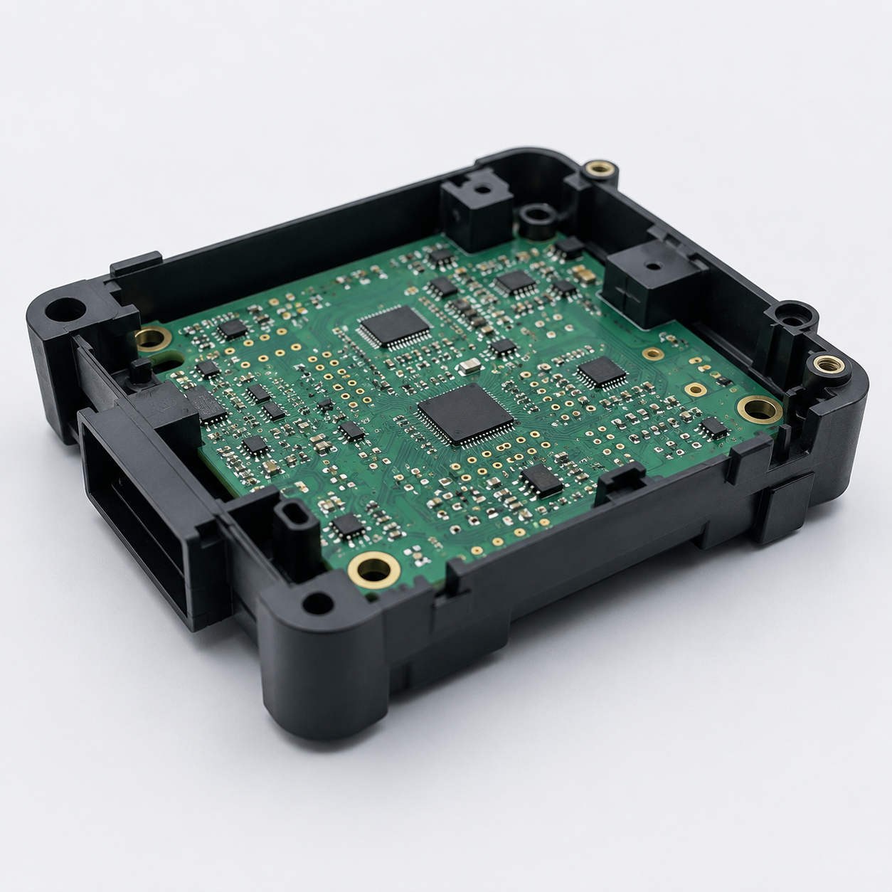
- PCB mounting position
- Hole alignment
- Internal clearance
Connector Assembly Check
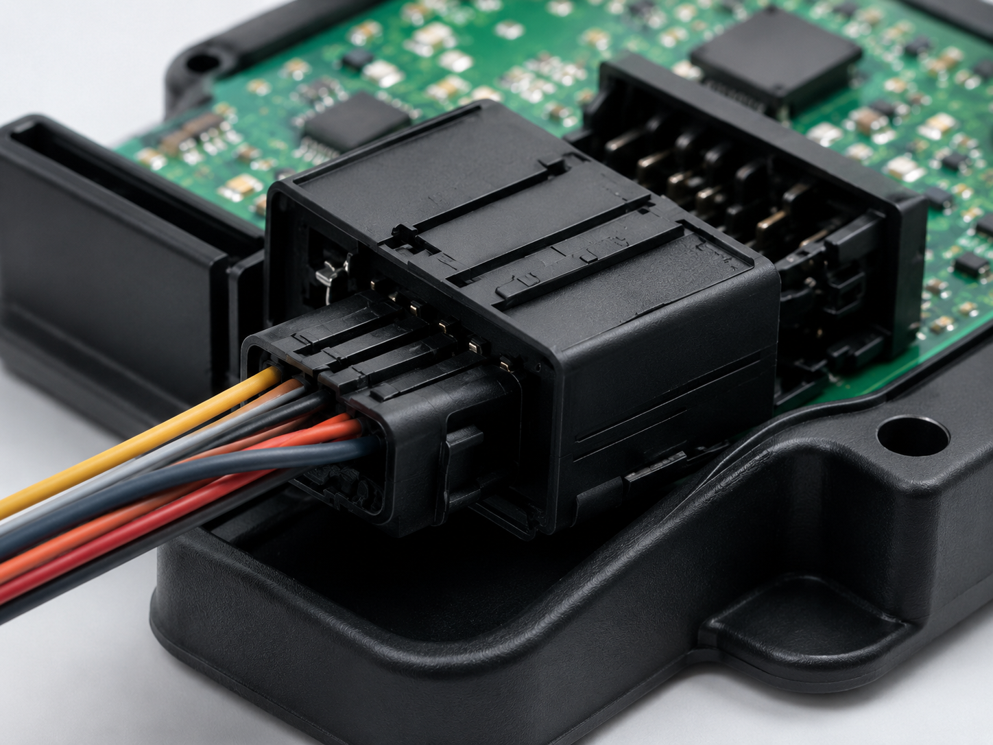
- Connector direction
- Plug-in space
- Locking condition
Cable Routing Check
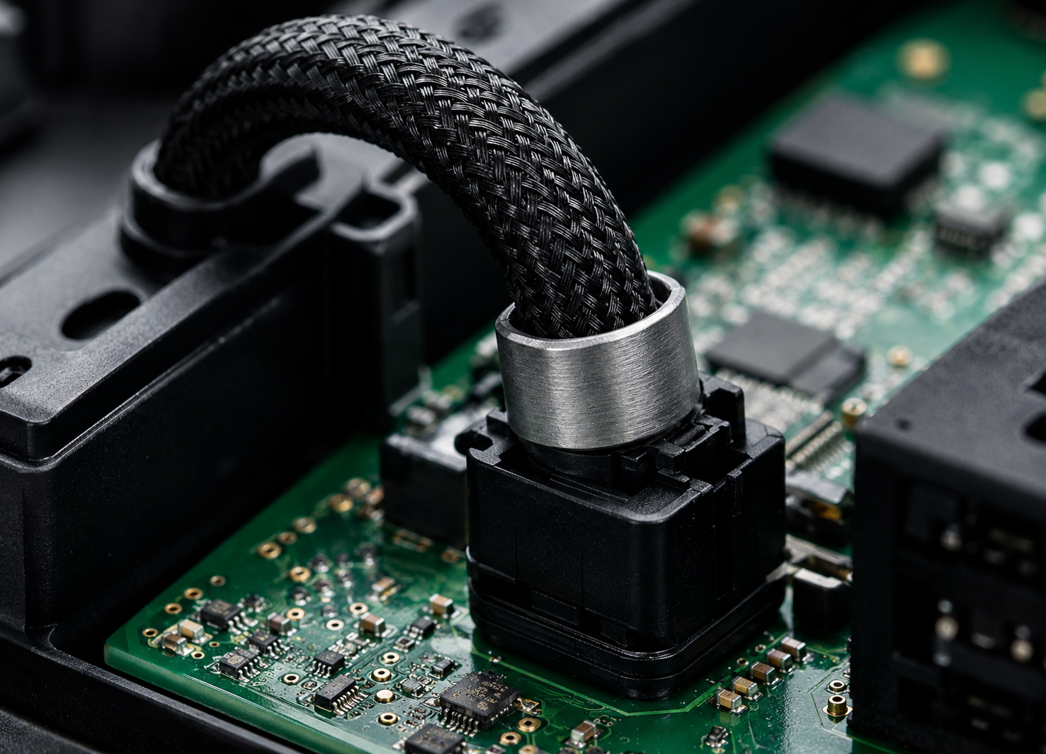
- Cable exit position
- Bend space
- Interference risk
Final Function Check
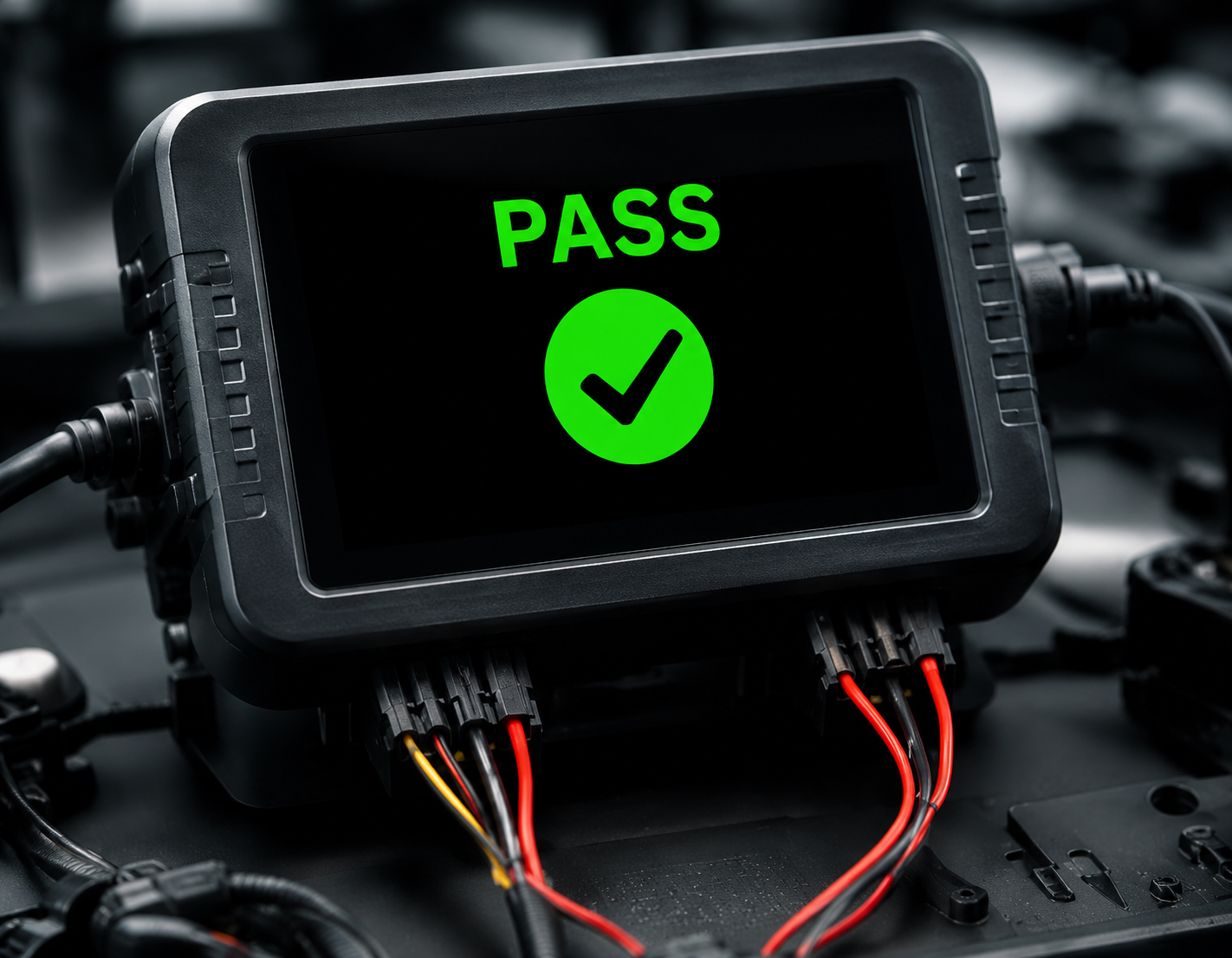
- Assembly fit
- Power or signal response
- Appearance before delivery
Controlled before shipment
Each production stage is checked against approved samples and project requirements to reduce assembly issues, installation problems, and avoidable rework.