BLOG / KNOWLEDGE CENTER

Manufacturing Insights & Engineering Guides

Practical articles about electronics manufacturing, PCBA, product assembly, DFM, testing, quality control, and OEM production decisions.

IML and IMR in Injection Molding

IML and IMR in Injection Molding: How In-Mold Decoration Impacts Cycle Time and OEE

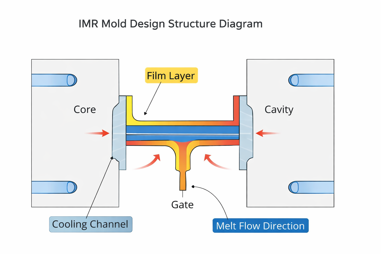
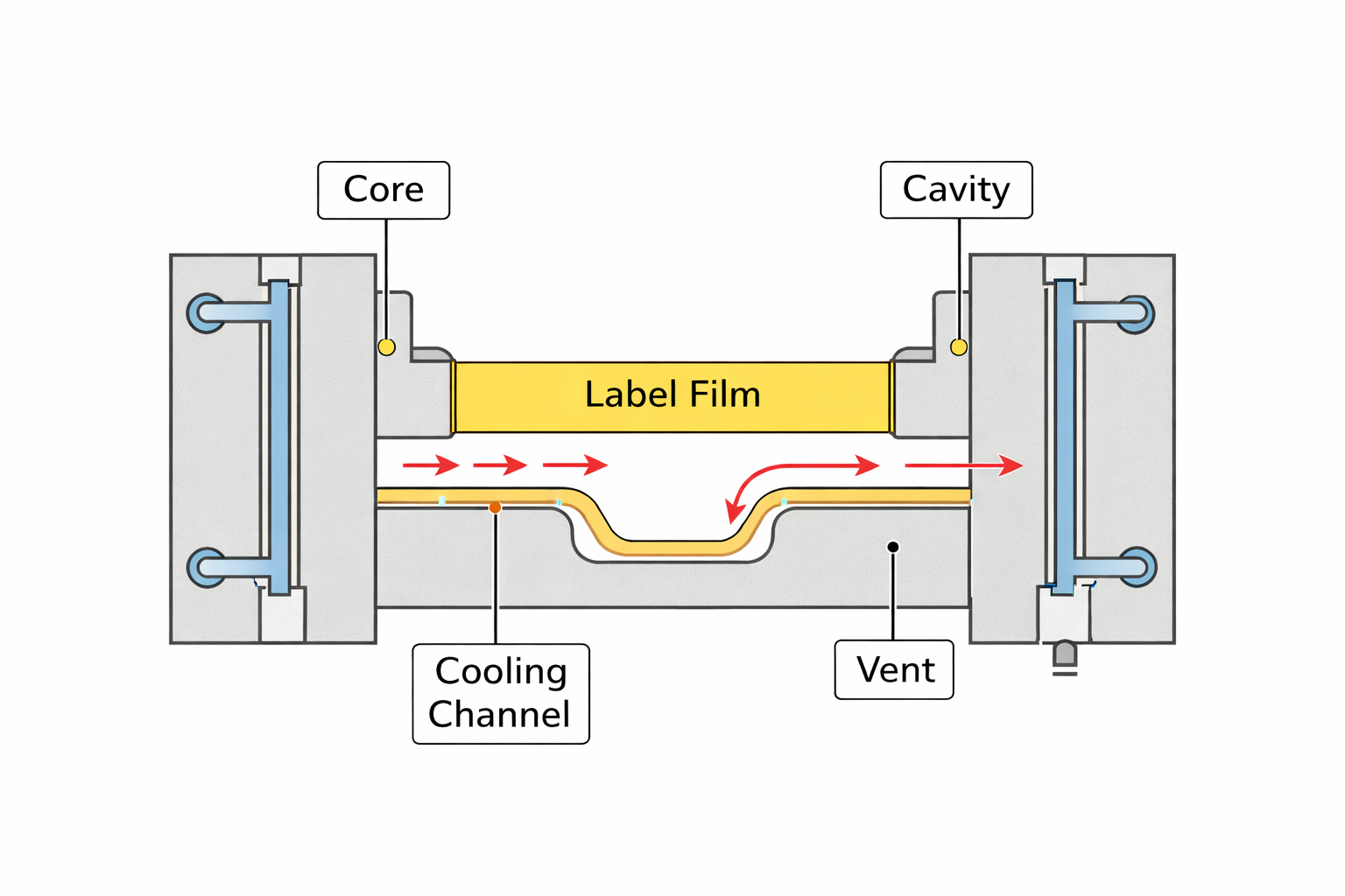
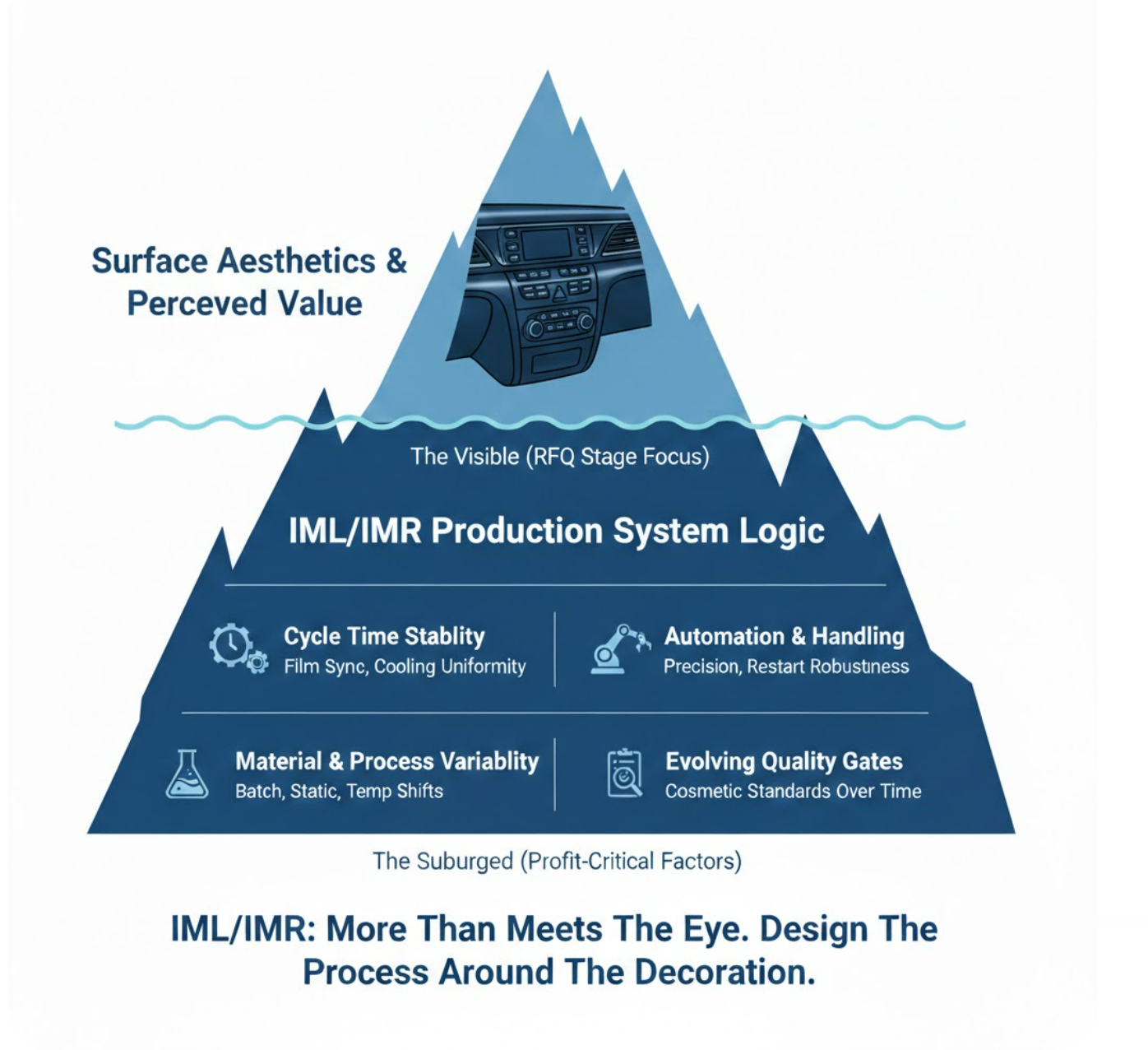
In many projects, IML and IMR are introduced as surface finishing upgrades. Better appearance.Improved durability.Elimination of secondary printing. Technically accurate. But in injection molding, IML injection molding and the IMR process are not simply decoration choices. They fundamentally change how the entire production system behaves. When in-mold decoration becomes part of the molding cycle, it reshapes: Projects rarely struggle because decoration is difficult.They struggle because decoration is treated as cosmetic — instead of structural. What Are IML and IMR in Injection Molding? IML (In-Mold Labeling) and IMR (In-Mold Roller Decoration) are both forms of in-mold decoration integrated directly into the injection molding process. In IML injection molding, a pre-printed label is inserted into the mold cavity before injection. The molten plastic bonds to the label during molding. In the IMR process, a continuous decorative film transfers ink onto the part surface during injection, synchronized with the molding cycle. In both cases: Decoration becomes inseparable from mold performance. Unlike post-molding printing or painting, surface appearance is no longer a downstream correction. It is locked into the molding cycle itself. That distinction is critical in mass production. How In-Mold Decoration Changes Injection Molding Cycle Time In conventional injection molding, cycle time is primarily controlled by cooling. Once the part solidifies sufficiently for ejection, the cycle resets. The dominant variables are: With IML and IMR, the cycle is no longer governed by cooling alone. Additional variables are introduced: Cycle time becomes a multi-variable coordination problem. A 0.5-second delay in film advancement is not cosmetic — it directly affects throughput and ROI. In IML injection molding, cycle stability depends not only on thermal balance but also on mechanical and automation precision. Automation Requirements in IML and IMR Production Standard injection molding can operate with minimal automation. IML and IMR cannot. Both processes depend heavily on: Automation is not optional support — it becomes a structural element of the process. Any deviation may cause: In a decoration-integrated process, a missed label is not just scrap.It becomes an OEE event. Availability, performance, and quality are all directly influenced. The Restart Effect in IML and IMR Mass Production One of the most underestimated risks in in-mold decoration is restart stability. In conventional molding, after a short stop, the system typically stabilizes within a few cycles. In IML and IMR production, restart behavior can be more complex. After downtime: Thermal stability and cosmetic stability are not always synchronized. This “restart effect” often reveals weaknesses that do not appear during short sampling trials. Mass production stability cannot be judged solely by steady-state validation. Why RFQ Cycle Time Estimates Are Often Inaccurate At the RFQ stage, IML and IMR cycle time is often estimated by adding a small buffer to conventional injection molding cycle logic. This approach assumes: In reality, in-mold decoration reduces tolerance to variation. Minor cooling imbalances or cavity pressure differences that are dimensionally acceptable in standard molding may become visible cosmetic defects in IML injection molding. When appearance becomes the primary quality gate, variability has higher cost. Optimistic cycle-time assumptions often fail under full production load. Multi-Cavity Mold Challenges in IML and IMR Projects Single-cavity trials frequently appear stable. Mass production rarely uses single-cavity tools. In multi-cavity injection molds, small variations are common: In conventional molding, these differences may not affect functionality. In IML or IMR production, they often appear as decorative inconsistency. Decoration amplifies cavity imbalance. The result may include: This is why cavity balance design is significantly more critical in in-mold decoration systems. Impact of IML and IMR on OEE and Production Stability OEE in injection molding depends on three components: IML and IMR affect all three. Availability:Automation downtime, feeder adjustments, or label misfeeds reduce uptime. Performance:Cycle-time stability depends on synchronization between mold, robot, and decoration system. Quality:Cosmetic defects often become primary rejection criteria. IML and IMR do not inherently reduce OEE.However, they narrow the acceptable process window. Stable decoration requires stable systems. Engineering IML and IMR for Long-Term Robustness Successful in-mold decoration projects share common engineering principles: Decoration should be treated as a boundary condition in mold design — not an afterthought. When decoration performance is engineered from the beginning, IML injection molding and IMR processes can deliver both efficiency and cosmetic consistency. When it is not, long-term instability becomes expensive to correct. When Should You Choose IML or IMR in Injection Molding? IML and IMR are strong choices when: They may be less suitable when: Choosing in-mold decoration is not simply a visual decision. It is a production system decision. Final Thoughts IML injection molding and IMR processes provide powerful advantages: But they also redefine production logic. Decoration affects cycle time.Decoration affects automation dependency.Decoration affects tolerance to variation.Decoration affects OEE. The question is not: “Can we implement IML or IMR?” It is: “Is our injection molding system designed to operate with decoration as a structural constraint?” That evaluation should happen before mold design is finalized — not after SOP. In injection molding, decoration is never just decoration. At CINDY Mould, we approach IML injection molding and IMR projects as system engineering challenges rather than surface decoration upgrades. Our capabilities include: Whether the requirement involves IML, IMR, multi-cavity molds, or high-volume injection molding, we focus on ensuring that decoration performance aligns with cycle-time logic and mass production robustness. If you are evaluating an IML or IMR project, early technical discussion often makes the greatest difference. We welcome engineering-level conversations before decisions are finalized. Follow us on LinkedIn

Read More »
Stack Molds

Stack Molds in Injection Molding: When Doubling Output Makes Sense — And When It Doesn’t

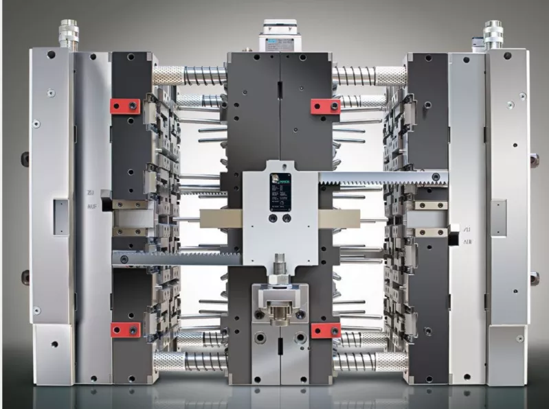
Stack molds in injection molding are often described as a way to double output without adding more machines. In theory, that statement is correct. In practice, the decision to use a stack mold is far more complex. At CINDY MOULD, we view stack molds not as a shortcut for productivity, but as a long-term production strategy. When properly engineered, a stack mold can significantly improve injection molding productivity and reduce cost per part. When poorly evaluated, it can introduce instability, excessive maintenance, and unnecessary capital risk. Understanding the difference is critical. What Is a Stack Mold in Injection Molding? A stack mold is a multi-level injection mold that contains two or more cavity layers within a single mold base. Unlike a traditional single-face mold, a stack mold produces parts on multiple parting lines during one injection molding cycle. In most configurations: The concept is straightforward. The engineering is not. Because the projected area effectively increases, clamp force requirements rise. Because cavities are duplicated, runner balance becomes more critical. Because cooling must be symmetrical, thermal management becomes more demanding. For a deeper review of structural balance, pressure equilibrium, and thermal control, see our guide to stack mold design for high-volume production. A stack mold is not simply “two molds in one.” It is a synchronized mechanical and thermal system. When Does a Stack Mold Make Sense? Not every injection molding project benefits from a stack mold configuration. Based on our engineering evaluations, stack molds are most suitable under the following conditions: 1. High-Volume, Long-Term Production Programs Stack molds require higher initial tooling investment compared to conventional molds. They are best justified when annual production volume is stable and long-term. If production forecasts are uncertain or product life cycles are short, the financial return may not offset the added complexity. 2. Balanced and Predictable Part Geometry Parts that are: are better suited for stack molds. Highly asymmetrical designs, complex undercuts, or tight cosmetic tolerances increase the difficulty of balancing multiple cavity layers. Early DFM analysis is essential before committing to a stack mold structure. 3. Adequate Injection Molding Machine Capacity A common misconception is that if clamp tonnage appears sufficient, the machine can run a stack mold. In reality, the following must be evaluated: Underestimating clamp force in stack mold projects is one of the most frequent technical mistakes. Even if flashing does not appear immediately, long-term mold wear and dimensional instability often follow. Key Engineering Considerations in Stack Mold Design Clamp Force Calculation Because stack molds increase total projected area, required clamp tonnage must be carefully calculated with sufficient safety margin. High cavity pressure applications, especially thin-wall parts, demand conservative engineering assumptions. A stack mold running near the upper limit of machine capacity may function during trial runs but struggle during mass production. Hot Runner and Flow Balance Flow balance is critical in stack mold injection molding. Both cavity layers must fill uniformly. Imbalance can lead to: Mold flow analysis should be conducted during the design stage, not after steel cutting. Cooling Symmetry and Cycle Time Optimization Cycle time reduction is often the primary motivation behind stack molds. However, cycle time improvements only materialize when cooling systems are symmetrically engineered. If cooling circuits are not mirrored between layers: Cooling design in stack molds must be treated as a system, not as duplicated circuits. Ejection System Synchronization In stack mold configurations, multiple sets of parts are ejected simultaneously. The ejection system must maintain alignment and rigidity over long production cycles. Poor synchronization may cause: Mechanical stability is as important as productivity. Cost Analysis: Does a Stack Mold Really Reduce Cost Per Part? Stack molds typically increase tooling cost by approximately 30–50% compared to a single-face mold with equivalent total cavity count. However, potential savings include: The true cost benefit depends on machine utilization rate and program stability. For high-volume consumer products or packaging applications, the return on investment can be achieved relatively quickly. For specialized or low-volume parts, a traditional mold configuration may be more economically sound. Stack molds reduce cost per part only when production conditions remain stable and predictable. Real Production Scenario: A Practical Comparison Consider a simplified example: Single-face mold: Stack mold configuration: Even with a slightly longer cycle, output per hour increases significantly. Over extended production runs, the effective cost per part decreases — provided quality and stability are maintained. The engineering challenge is ensuring that productivity gains are not offset by downtime or scrap. Common Misconceptions About Stack Molds “Stack molds automatically halve cost per part.”Not always. Energy consumption, maintenance complexity, and machine wear must be included in cost calculations. “Any high-volume part should use a stack mold.”Volume alone does not determine suitability. Part geometry and machine compatibility are equally important. “Stack molds are just duplicated cavities.”In reality, stack molds require integrated mechanical, thermal, and flow system design. Frequently Asked Questions About Stack Molds How much clamp force does a stack mold require? Clamp force depends on total projected area and injection pressure. Because stack molds increase projected area, required tonnage often rises substantially. Detailed engineering calculation is necessary before machine selection. Are stack molds suitable for thin-wall injection molding? They can be, but thin-wall applications require careful pressure analysis and balanced hot runner systems. Clamp force margins must be conservative. What industries commonly use stack molds? Stack molds are frequently used in packaging, consumer goods, and high-volume plastic housings where production efficiency is critical. When should stack mold decisions be made? Stack mold strategy should be evaluated during the DFM stage, alongside part design and production planning — not after mold construction begins. Stack Molds as a Strategic Production Decision Stack molds in injection molding are powerful tools when applied correctly. They can increase output, optimize factory space, and reduce cost per part. But they are not universal solutions. At CINDY MOULD, we approach stack mold projects through structured engineering validation — including clamp force calculation, flow simulation, cooling layout study, and long-term maintenance assessment. Follow us on LinkedIn

Read More »
Mold wear and tear in high-volume injection molding

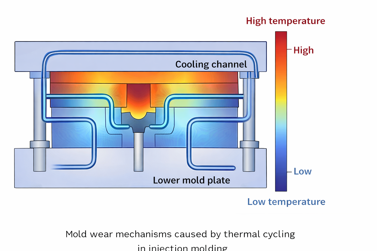
Mold Wear and Tear: How to Extend Mold Life in High-Volume Production

In high-volume injection molding, mold wear and tear is rarely treated as a design issue until production becomes unstable.
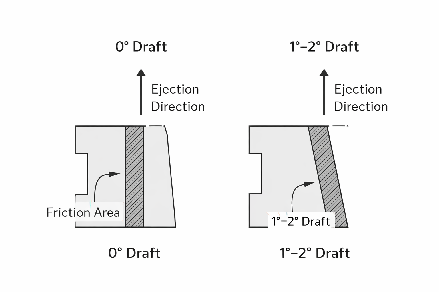
This article explains why mold wear accelerates over time, how it is often misdiagnosed as a maintenance problem, and which early design and process decisions most effectively extend mold life in mass production.

Read More »
START YOUR PROJECT

Have a Manufacturing Project to Discuss?

From PCBA and product assembly to functional testing and final delivery, CINDY MOULD supports OEM projects with practical manufacturing experience and responsive communication.