In injection mold design, the parting line (PL) is often misclassified as a trivial structural detail—one that’s rushed through during the initial concept phase. However, PL placement and geometry decisions made early in the design cycle have a cascading impact on:
- Mold robustness
- Part dimensional stability
- Surface finish integrity
- Total cost of ownership (TCO)
This is especially true for molds that undergo high-volume production (e.g., commodity resins like PP/PE, engineering resins like PC/ABS), where the mold life can range from 500,000 to 2 million cycles.
The parting line dictates:
- Mold opening/closing kinematics
- Clamping force (Fclamp) distribution across the mold base
- Repeatability of part quality in mass production
While a minor design call during CAD modeling—like shifting a PL by 5–10mm or changing its profile—may seem insignificant, it can lead to recurring production headaches once the mold is commissioned. These issues, such as excessive flash, part sticking, ejector pin scoring, or premature mold wear, typically escalate in mass production, affecting profit margins and time-to-market.
This article dives into the critical, often underemphasized role of parting line design in injection mold engineering, breaks down common failures stemming from improper PL placement, and outlines actionable design guidelines.
For additional discussions on mold design considerations and DFM-related risk control, related technical articles can be found in our Design & DFM knowledge section:
👉 https://cindy-mould.com/category/design-dfm/
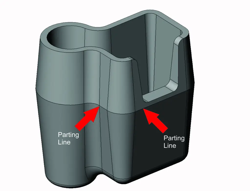
The Core Role of Parting Lines in Injection Mold Performance
The parting line is the mating interface between the stationary half (A-side, cavity side) and moving half (B-side, core side) of the mold. Its position, profile, and surface finish directly influence several key mold performance aspects:
For additional discussions on mold design considerations and DFM-related risk control, related technical articles can be found in our Design & DFM knowledge section:
👉 https://cindy-mould.com/category/design-dfm/
1. Mold Closure Precision
- Ensures the mold halves close properly and evenly
- Ensures proper sealing of the cavity to avoid leakage
2. Ejection Efficiency
- Affects how smoothly parts are ejected from the mold
- Improper placement can cause resistance during demolding
3. Cavity Pressure Distribution
- Helps achieve uniform pressure across the mold
- Prevents localized high-pressure zones that lead to wear
4. Long-Term Mold Maintainability
- Well-designed parting lines reduce wear and the frequency of maintenance
- Poorly designed parting lines increase the likelihood of costly rework
Mold Closure and Clamping Force Optimization
The parting line is crucial for ensuring uniform clamping force distribution. An improperly designed PL can lead to:
- Localized pressure hotspots: Areas that experience excessive clamping force, leading to accelerated wear.
- Cold spots: Areas with insufficient clamping force, resulting in improper sealing.
Key issues caused by poor PL design:
- Uneven shut-off heights or abrupt transitions in the PL can cause inconsistent clamping force.
- Pressure imbalances lead to mold flash and increased wear on mold inserts, cavity/core steel, and guide pins.
Solution:
- Align the parting line with the center of pressure (CoP) to evenly distribute the clamping force.
- For thin-walled parts, small clamping force imbalances can lead to warpage or mold deflection. Correct PL design reduces this risk.
Demolding Efficiency and Ejection Stress Mitigation
The alignment of the parting line with the part’s draw direction is crucial for:
- Minimizing ejection resistance (measured in kN)
- Avoiding part damage during the demolding process
Issues from poor PL alignment:
- Parting line conflicts with the part’s draw direction, creating undercuts or requiring complex side actions.
- Ejector pin positioning: When the PL is too close to critical features, it forces ejector pins into high-stress areas, leading to part deformation or pin damage.
Solution:
- Ensure the PL is parallel to the part’s primary draw direction to minimize resistance and avoid part damage.
- Optimize ejector pin spacing to distribute forces evenly across the part.
Mold Maintenance and Service Life Extension
A well-designed parting line helps extend the mold’s service life by reducing the frequency of repairs and maintenance.
Common maintenance issues from poor PL design:
- Frequent re-polishing of shut-off surfaces due to flash formation.
- Replacement of worn ejector pins, sliders, or guide components.
These lead to:
- Increased maintenance costs (10-20% of TCO)
- Unplanned downtime (typically $500–$2,000 per hour in high-volume production)
Solution:
- Design parting lines that are easy to access for maintenance.
- Avoid sharp corners that trap resin and cause wear.
- Use wear plates for high-stress areas to extend mold life.
From a broader injection molding process perspective, mold separation and sealing behavior are fundamental to overall molding stability, as discussed in industry publications such as Plastics Technology:
👉 https://www.ptonline.com/
Common Failures from Improper Parting Line Design
Improper PL design is responsible for approximately 30% of injection mold production defects and 25% of unplanned downtime. Many of these failures only become apparent after significant wear during production cycles (10,000+ cycles). Below are some of the most common issues caused by improper PL placement:
1. Flash and Burr Formation (Most Prevalent Defect)
- Flash occurs when molten resin escapes between mold halves during clamping.
- It is often caused by uneven shut-off heights, insufficient clamping force, or incorrect PL placement.
Real-World Example:
- PP Automotive Trim Part: The PL was placed across a thin-walled section (1.2mm wall thickness), causing a 0.02mm shut-off height variation. After 8,000 cycles, flash appeared, increasing scrap rate from 1% to 8% and adding 12 seconds to each cycle.
- Solution: Adjusting the injection pressure temporarily mitigated the issue, but mold wear continued to widen the shut-off gap, requiring rework after 30,000 cycles, costing $8,000 and 48 hours of downtime.
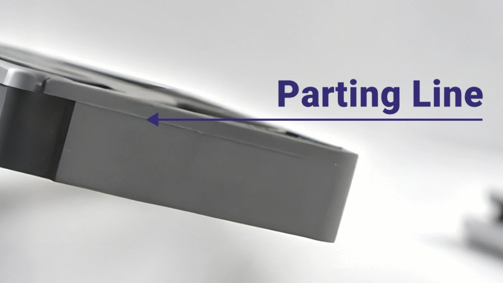
2. Cosmetic Defects and Surface Finish Inconsistencies
Improper PL placement near cosmetic surfaces can create visible parting lines (seams) on the part surface.
Example:
- PC/ABS Smartphone Back Cover: The PL was placed along the visible edge of the cover. While prototype runs showed acceptable surface finish, mass production revealed a visible seam due to mold wear, resulting in a 15% scrap rate and $50,000 in losses.
Solution:
- Relocate PL to non-visible areas or use a stepped PL to hide seams.
3. Demolding Failures and Ejection System Damage
Misaligned PLs create resistance during demolding, leading to ejector pin bending and part sticking.
Example:
- PBT/GF Automotive Connector: The PL was perpendicular to the draw direction, causing excessive ejection force. Frequent ejector pin bending and part sticking led to 15% downtime and high maintenance costs.
Solution:
- Re-align PL with the draw direction and optimize ejector pin positioning to reduce stress.
4. Accelerated Mold Wear and Reduced Service Life
Improper PL design accelerates wear on the mold, requiring more frequent repairs.
Example:
- PE Bottle Cap Mold: The PL had sharp 90° corners at the shut-off surface. After 50,000 cycles, the mold required re-polishing every 10,000 cycles, costing $500 per polish.
Solution:
- Use wear plates in high-stress shut-off areas and smooth the PL corners to reduce stress concentrations.
Practical Design Principles for Robust Parting Lines
To avoid the failures mentioned above, mold designers should:
- Prioritize Part Aesthetics and Functional Requirements
- Relocate PL away from visible surfaces for cosmetic parts.
- Align PL with Draw Direction and Optimize Draft Angles
- Ensure PL is parallel to the part’s primary draw direction.
- Ensure Uniform Clamping and Cavity Pressure Distribution
- Use a stepped PL for better seal-off and consistent pressure.
- Design for Maintainability and Service Life
- Make the PL easy to access for maintenance and avoid sharp corners.
Conclusion
The parting line is a critical element in injection mold design, influencing mold performance, part quality, and long-term mold maintenance. Early attention to parting line design can help prevent common issues, reduce maintenance costs, and improve mold longevity.
By prioritizing proper PL placement, aligning it with part geometry and resin properties, and designing for maintainability, mold engineers can significantly reduce production defects, extend mold life, and lower total cost of ownership.