Introduction
Cold solder joint PCB repair is a critical process in electronics manufacturing, especially when defects lead to intermittent failures and reduced product reliability. These defects often result in unstable electrical performance and premature product breakdown. Unlike obvious issues, cold solder joints may pass initial inspection and functional testing, only to fail later during real-world operation.
In high-volume production environments, even a small percentage of cold solder joints can significantly impact yield, increase rework rates, and delay delivery schedules. This makes effective repair strategies essential not only for product quality but also for cost control and operational efficiency.
In many cases, cold solder joint PCB repair becomes necessary to restore product performance and ensure reliability in production.
What Is a Cold Solder Joint (Brief Overview)
A cold solder joint is formed when solder does not fully reflow or properly wet both the PCB pad and the component lead. According to IPC standards, proper solder joint formation is critical for ensuring long-term reliability in electronic assemblies. Instead of forming a strong metallurgical bond, the connection remains weak, uneven, or partially bonded.
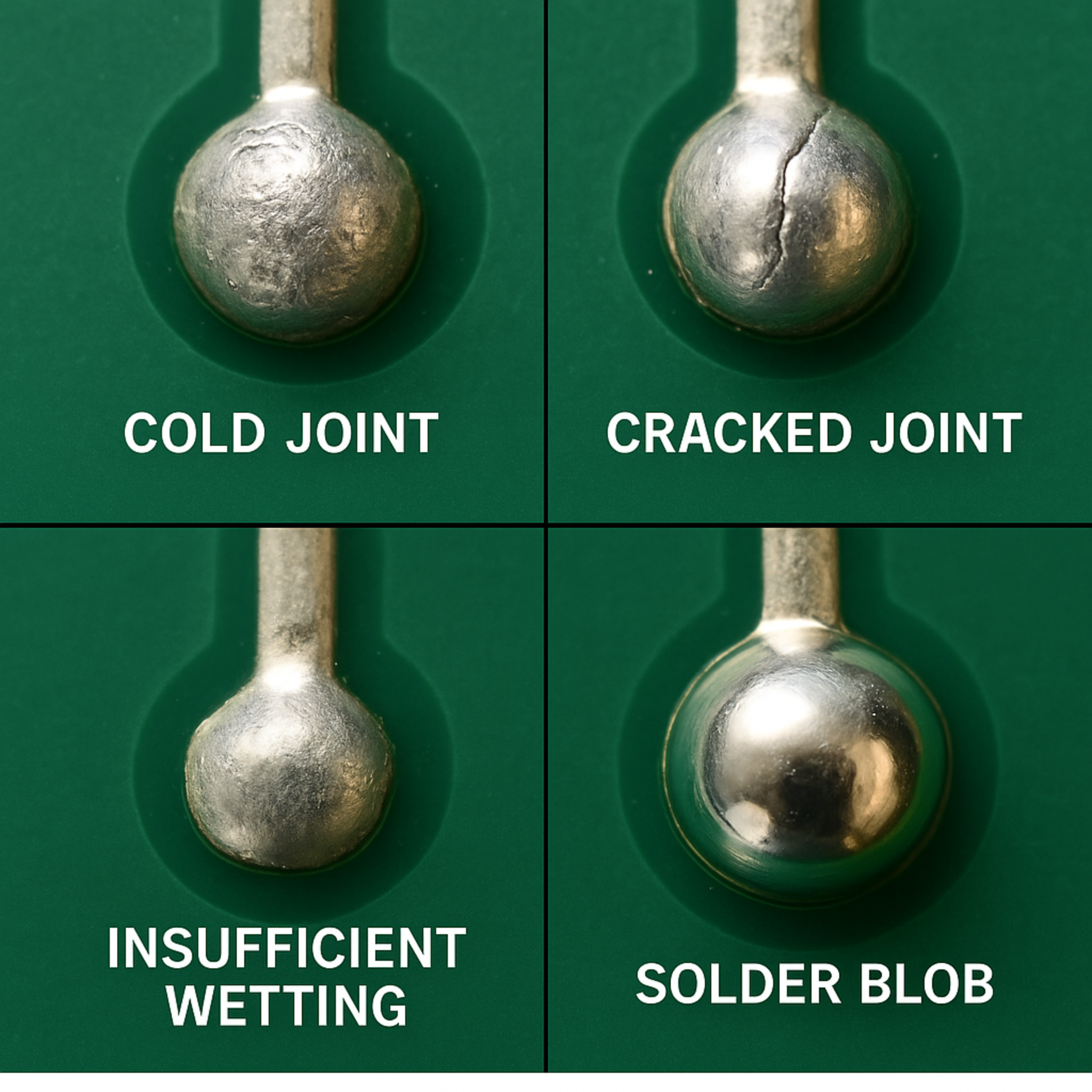
Typical characteristics include:
- Dull or matte surface appearance
- Poor wetting between solder and metal surfaces
- Irregular or rough solder shape
- Micro-cracks that may develop under stress
These defects may initially appear acceptable but often lead to unstable electrical connections and reduced mechanical strength.
To better understand the root causes behind these defects, you can refer to our detailed guide on cold solder joint PCB causes and prevention.
Why Cold Solder Joints Must Be Repaired
Cold solder joints are not cosmetic defects—they represent a fundamental process failure that directly affects product reliability.
Intermittent Electrical Failures
A product may function normally during testing but fail under real operating conditions due to:
- Mechanical vibration
- Thermal expansion and contraction
- Repeated power cycling
These failures are difficult to diagnose and often lead to customer complaints.
Increased Electrical Resistance
A poorly formed solder joint increases resistance within the circuit, which can cause:
- Signal instability
- Voltage drops
- Reduced efficiency
Mechanical Instability
Cold solder joints lack sufficient mechanical strength and may fail during:
- Transportation and handling
- Assembly into enclosures
- Long-term operation
Impact on Production Cost and Customer Satisfaction
If defects are not corrected:
- Rework costs increase
- Delivery timelines are affected
- Warranty claims rise
- Brand reputation is damaged
Cold Solder Joint PCB Repair Methods and Rework Techniques
Cold solder joint PCB repair requires a combination of proper tools, process control, and operator experience to achieve reliable results.
Reheating the Existing Joint
For minor defects, reheating may be sufficient to restore proper bonding.
Process:
- Apply controlled heat using a soldering iron or rework station
- Allow the solder to fully reflow
- Maintain adequate dwell time
Removing and Re-Soldering
For more severe defects, complete rework is necessary.
Steps:
- Remove old solder using desoldering braid or pump
- Clean the pad and component lead
- Apply flux
- Add fresh solder
- Ensure smooth and complete wetting
Using Flux to Improve Wetting
Flux is essential for removing oxidation and promoting solder flow.
- Apply flux before heating
- Use the correct flux type
- Ensure flux is not degraded
Temperature Control During Rework
Temperature must be carefully controlled:
Understanding the reflow soldering process is essential for setting proper temperature profiles and avoiding solder joint defects.
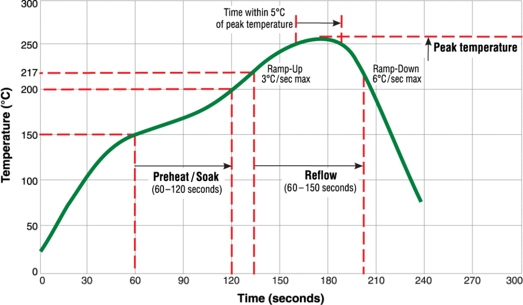
- Too low → incomplete solder melting
- Too high → PCB damage or component failure
Avoiding Movement During Solidification
After reflow, the solder joint must remain completely stable until it solidifies.
- Avoid handling the PCB
- Prevent vibration
- Allow sufficient cooling time
Repair Methods Comparison
| Method | Suitable Scenario | Advantages | Risks |
|---|---|---|---|
| Reheating | Minor defects | Fast, low cost | May not fully restore reliability |
| Re-soldering | Moderate defects | Strong and stable | Requires skilled operation |
| Flux-assisted repair | Oxidation issues | Improves wetting | Residue contamination |
| Component replacement | Severe defects | Highest reliability | Higher cost |
When a Cold Solder Joint Cannot Be Repaired
Not all defects are suitable for repair.
- Severe oxidation prevents proper solder bonding
- PCB pad damage leads to unstable connections
- Component degradation reduces reliability
- Multiple rework cycles increase failure risk
Rework vs Scrap Decision Guide
| Condition | Recommended Action |
|---|---|
| Single localized defect | Rework |
| Multiple defects | Scrap |
| Structural damage | Scrap |
| High-reliability product | Replace or scrap |
| Cost-sensitive production | Controlled rework |
Process Control and Rework Management in Production
In mass production environments, cold solder joint PCB repair must be standardized to ensure consistent quality and reduce defect rates.
Manufacturers should:
- Define acceptable rework limits
- Standardize repair procedures
- Monitor rework rates
- Track defect trends and root causes
A high rework rate often indicates upstream process instability, emphasizing the importance of early-stage quality control.
Best Practices to Reduce Rework in Production
Reducing defects at the source is always more cost-effective than repairing them later.
Optimizing the soldering process is essential. You can also explore how reflow soldering profiles affect PCB assembly quality to further improve process stability.
- Optimize reflow temperature profiles
- Improve material storage conditions
- Maintain a clean production environment
- Strengthen inspection systems
- Standardize operator procedures
- Apply DFM principles early
Risk Control in Mass Production
In high-volume production, even small process variations can lead to large-scale defects.
Key strategies include:
- Implementing statistical process control (SPC)
- Monitoring temperature profiles in real time
- Conducting regular process audits
- Ensuring material consistency
Real Manufacturing Insight
In real production environments, cold solder joint PCB repair is more common during scale-up than during initial prototyping.
A typical scenario involves a product performing well during pilot runs but showing increased defect rates after mass production begins. Common causes include:
- Slight temperature profile deviations
- Variations in solder paste batches
- Environmental fluctuations such as humidity
Consistency across production batches is essential for maintaining long-term reliability.
Understanding common PCB assembly defects beyond cold solder joints can also help improve overall product quality and reduce production risks.
Frequently Asked Questions
What is the most effective way to perform cold solder joint PCB repair
Reheating or complete re-soldering with proper temperature control and fresh materials is the most effective method.
Can repaired solder joints be as reliable as new ones
Yes, when properly repaired, they can achieve comparable reliability.
How many times can a solder joint be reworked
Rework should be limited, as repeated repair increases failure risk.
Does rework affect PCB lifespan
Improper or excessive rework can reduce long-term reliability.
What tools are required for repair
Typical tools include a temperature-controlled soldering iron, rework station, flux, solder wire, and inspection equipment.
Conclusion
Cold solder joint defects are a critical but manageable challenge in electronics manufacturing. Proper repair methods such as reheating, re-soldering, and flux-assisted processes can effectively restore solder joint integrity.
However, not all defects should be repaired. Understanding when to rework and when to scrap is essential for maintaining both product reliability and production efficiency.
Ultimately, the goal is not only to fix defects but to minimize their occurrence through consistent process control, stable materials, and experienced engineering practices.
Cold solder joint PCB repair plays a critical role in maintaining consistent product quality and ensuring long-term reliability in PCB assembly.