Introduction
Reflow soldering profile plays a critical role in PCB assembly reliability and overall product performance.
In electronics manufacturing, product reliability is often associated with component quality, PCB design, or inspection systems such as AOI and X-ray.
However, many real-world failures originate from a less visible but highly influential process:
👉 reflow soldering.
A PCB assembly may pass SPI, AOI, and even functional testing, yet still experience intermittent failures, unstable performance, or early-life breakdown in actual applications. These issues are often difficult to trace because no single stage appears to be clearly “incorrect.”
In many cases, the root cause lies in how the reflow soldering profile is controlled during production.
A well-controlled reflow soldering profile ensures consistent solder joint formation and stable production outcomes.
Reflow is not simply about heating a PCB. It is a precisely controlled thermal process that determines how solder paste activates, melts, wets, and solidifies. Small deviations in temperature, timing, or heat distribution can result in significant variation in solder joint quality.
These variations may not be immediately visible, but they directly influence electrical stability, mechanical strength, and long-term reliability.
Effective control of the reflow soldering profile is therefore essential for achieving consistent and repeatable PCB assembly outcomes — especially in mass production environments.
What Is a Reflow Soldering Profile and How Does It Work?
A reflow soldering profile describes how temperature changes over time as a PCB travels through a reflow oven.
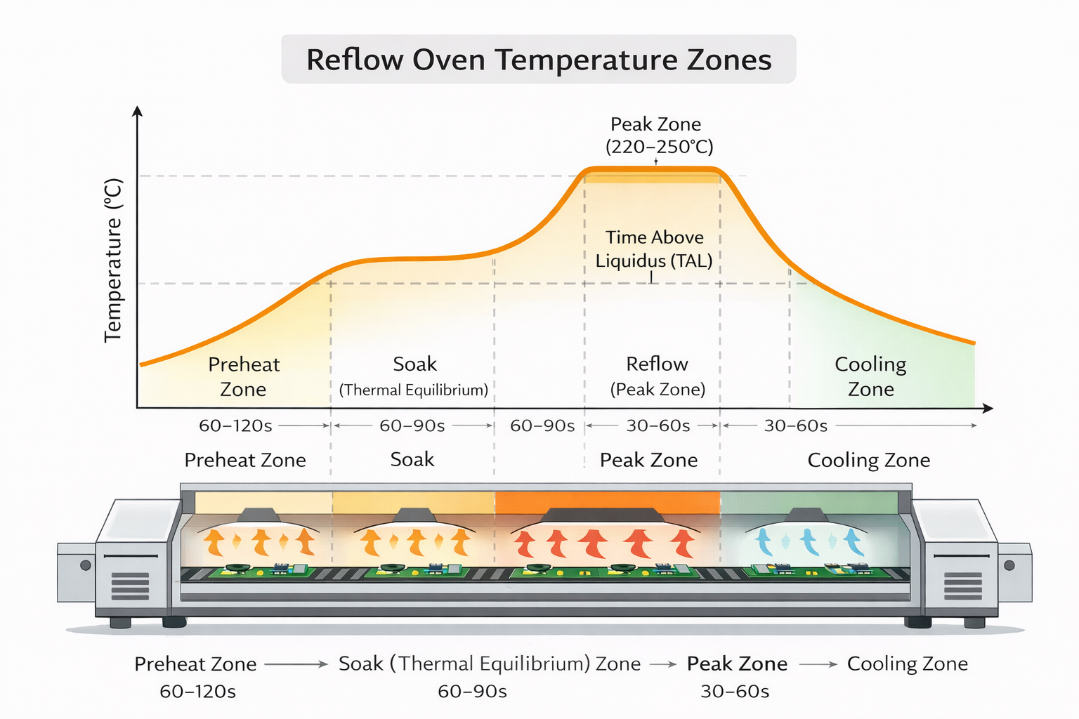
This process is typically divided into four key stages:
- Preheat
- Soak (Thermal Equilibrium)
- Reflow (Peak Zone)
- Cooling
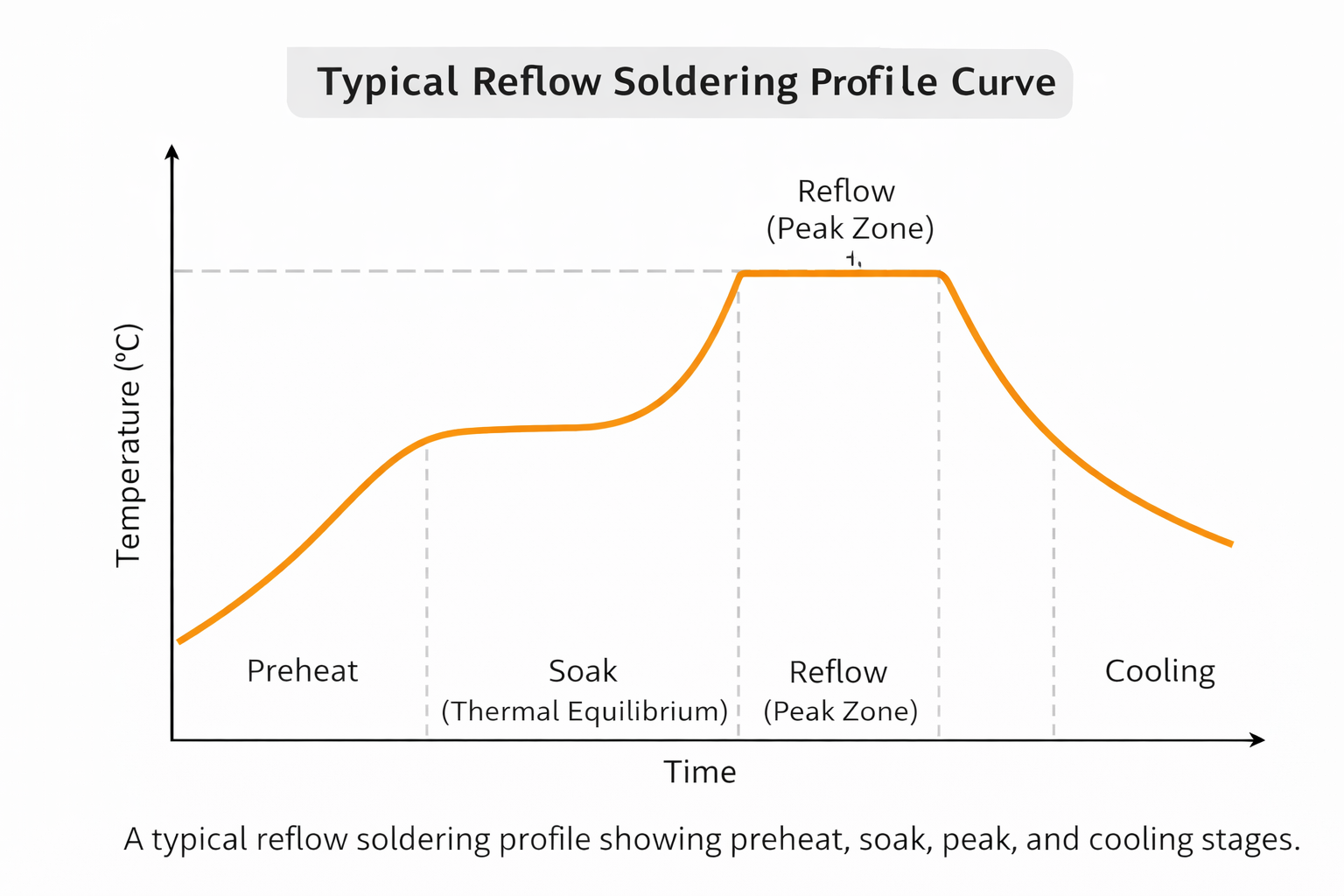
Each stage plays a specific role in preparing the solder paste and forming reliable solder joints.
Rather than being a simple heating curve, the reflow soldering profile is a time–temperature relationship that must be carefully controlled within defined limits.
Even when the same profile is programmed into the oven, the actual temperature experienced by the PCB can vary due to:
- board thickness and copper density
- component size and distribution
- thermal mass differences
- airflow variations inside the oven
This highlights that a reflow soldering profile is not only a machine setting, but a reflection of real thermal behavior at the board level.
🔧 Key Parameters in a Reflow Soldering Profile
Different parameters within a reflow soldering profile interact to determine process stability and final product reliability.
A reflow soldering profile is not controlled by a single variable, but by the interaction of multiple thermal parameters, including temperature ramp rate, soak duration, peak temperature, time above liquidus, and cooling rate.
These parameters must be carefully balanced to ensure uniform heat distribution and consistent solder joint formation across the PCB.
Industry standards such as IPC guidelines provide important references for defining acceptable temperature ranges and process control in reflow soldering.
1. Preheat Rate
The preheat stage gradually increases the PCB temperature at a controlled ramp rate.
If the heating rate is too fast:
- components may experience thermal shock
- moisture expansion can cause micro-cracks
- PCB warpage may occur
If too slow:
- flux activation may be incomplete
- oxidation may not be effectively removed
👉 A stable preheat stage ensures smooth transition into the reflow phase.
2. Soak Temperature and Time
The soak stage allows temperature across the PCB to equalize and activates flux.
Poor soak control can lead to:
- uneven solder melting
- inconsistent wetting
- weak electrical connections
👉 Soak stability is essential for uniform solder joint formation.
3. Peak Temperature
Peak temperature determines whether solder fully melts.
If too low:
- incomplete soldering
- weak joints
If too high:
- component damage
- excessive IMC growth
👉 Peak temperature must align with solder paste specifications.
4. Time Above Liquidus (TAL)
TAL defines how long solder remains molten.
Too short:
- insufficient wetting
Too long:
- oxidation
- brittle joints
👉 TAL directly impacts solder joint integrity.
5. Cooling Rate
Cooling determines final solder structure.
Too fast:
- internal stress
- micro-cracks
Too slow:
- reduced mechanical strength
👉 Controlled cooling is critical for long-term reliability.
📉 How an Unstable Reflow Soldering Profile Causes Defects
An unstable reflow soldering profile is one of the main causes of soldering defects.
Common defects include:
- Tombstoning
- Solder bridging
- Voids
- Cold joints
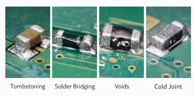
These issues are commonly categorized as PCB assembly defects and are often linked to variations in the reflow soldering profile during production.
These defects often originate from:
- uneven heating
- inconsistent flux activation
- thermal imbalance
In high-density PCB assemblies, differences in thermal mass can further amplify these effects.
Some defects may pass inspection but fail later under:
- thermal cycling
- vibration
- mechanical stress
These defects are typically identified through the SMT inspection process, including SPI, AOI, and AXI, which help detect issues at different stages of PCB assembly.
👉 This highlights the importance of maintaining a stable reflow soldering profile rather than relying solely on inspection.
🔗 Why Reflow Stability Impacts the Entire Manufacturing System
The reflow soldering profile is a central element in SMT production.
It directly influences:
- inspection results
- assembly consistency
- functional testing performance
- long-term product reliability
For example:
- marginal joints may pass AOI but fail during functional testing, which are typically identified through the SMT inspection process
- inconsistent soldering affects final assembly stability
This becomes especially critical during the final assembly process, where mechanical integration and electrical connections must remain consistent across production batches.
📊 Process Variation and Mass Production Challenges
Even with a defined reflow soldering profile, variation can occur due to:
- PCB design differences
- component density
- oven loading conditions
- equipment drift
These variations are not always visible in short-term testing but can significantly impact long-term performance consistency.
Over time, they can accumulate and lead to:
- batch inconsistency
- yield fluctuation
- performance variation
👉 In mass production, consistency is the real challenge.
📈 How to Optimize a Reflow Soldering Profile
Reflow soldering profile optimization is essential for stable and scalable production.
Key actions include:
- defining target temperature curves
- validating profiles with real PCB measurements
- maintaining equipment calibration
- standardizing process setup
- controlling solder paste conditions
- monitoring process drift
A well-optimized reflow soldering profile ensures:
- consistent solder quality
- reduced defect rates
- stable production output
🧠 Why Reflow Issues Often Go Unnoticed
Reflow-related issues often do not cause immediate failure.
Instead, they create:
- marginal solder joints
- hidden risks
- unit-to-unit variation
Problems may only appear after:
- extended use
- environmental stress
- mechanical load
👉 This delayed effect makes controlling the reflow soldering profile even more critical.
Conclusion
The reflow soldering profile serves as a critical bridge between process parameters and real product performance.
It transforms thermal control into actual solder joint quality, influencing both immediate functionality and long-term reliability.
For this reason, maintaining a stable and well-controlled reflow soldering profile is not only a process requirement, but a key factor in achieving scalable and predictable manufacturing results.