
A quality checklist should follow the product—not the other way around.
Electronic products may pass through similar manufacturing stages but still require different inspection plans. A smart control panel may prioritize display response and appearance, while an industrial controller may emphasize connector security and thermal performance. A sealed outdoor device may require gasket and water-resistance checks.
Using one generic checklist for every project can leave important risks uncovered while creating unnecessary inspections in low-risk areas.
Effective quality control in electronics manufacturing begins by identifying what is critical for a specific product. The manufacturer must then define where each requirement will be checked, how it will be measured, what result is acceptable, how many units will be inspected, who is responsible, and what action follows a failed result.
This guide explains how to build a product-specific inspection plan for electronic products involving PCBAs, plastic enclosures, cables, firmware, testing, final assembly, and packaging.
What Is a Quality Control Plan in Electronics Manufacturing?
A quality control plan converts product requirements into practical inspection and testing activities.
It should answer seven questions:
- What must be inspected or tested?
- At which stage should it be checked?
- Which method or tool should be used?
- What is the acceptance criterion?
- How many units should be inspected?
- Who is responsible?
- What happens when a result fails?
The plan should allow different inspectors to reach the same conclusion.
“Check product appearance” is too general. A useful instruction should identify critical surfaces, unacceptable defects, inspection conditions, and reference samples. Likewise, “verify product function” should define the test input, operating steps, expected response, measurement range, and pass/fail criteria.
ASQ’s guidance on quality plans describes a quality plan as a way to translate requirements into procedures, responsibilities, tolerances, test parameters, and acceptance criteria.
In practical quality control in electronics manufacturing, the plan connects engineering requirements with purchasing, production, testing, inspection, and product release.
Why One Quality Checklist Cannot Fit Every Electronic Product
Generic checklists are useful starting points, but they cannot fully define every product risk.
Different products may prioritize:
- Electrical performance
- PCB and enclosure fit
- Wireless communication
- Connector security
- Waterproofing
- Thermal performance
- Cosmetic appearance
- Firmware configuration
- Packaging protection
Even similar PCBAs may require different inspections because the enclosure, software, environment, and service requirements differ.
A product-specific approach to quality control in electronics manufacturing prevents two common problems:
- Important risks are missing from a standard checklist.
- Low-risk characteristics are repeatedly checked without adding meaningful protection.
For quality control in electronics manufacturing, the plan should begin with approved product requirements and risk, not a fixed factory template.
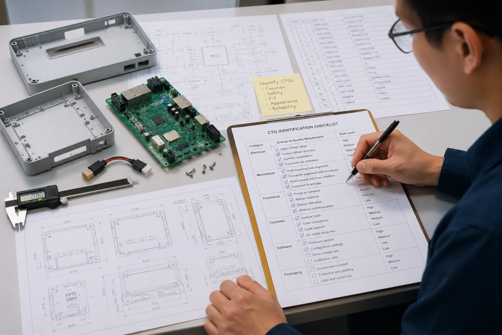
1. Identify the Critical-to-Quality Requirements
In quality control in electronics manufacturing, Critical-to-Quality requirements, or CTQs, are characteristics that must be controlled for the product to meet its intended function, appearance, fit, safety, and customer expectations.
CTQs should be identified from:
- Product specifications
- PCB and assembly drawings
- Bill of materials
- Mechanical drawings
- Firmware requirements
- Functional test specifications
- Approved samples
- Product-use conditions
- Packaging instructions
- Customer and regulatory requirements
CTQs can be grouped into six areas:
- Electrical: voltage, current, continuity, communication, charging, and sensor response
- Mechanical: PCB fit, mounting-hole alignment, connector openings, screws, cables, gaps, and snap-fits
- Functional: power-on behavior, buttons, displays, wireless links, motors, relays, alarms, and timing
- Cosmetic: scratches, color, molding marks, printing, labels, and visible gaps
- Software: firmware version, product configuration, serial number, calibration, and regional settings
- Packaging: accessories, protection, labels, carton quantity, and shipping marks
These priorities keep quality control in electronics manufacturing focused on CTQs affecting function, safety, compatibility, assembly, customer use, or release.
2. Convert Product Risks into Inspection Items
Once CTQs are identified, each risk should become a clear inspection or test item. This gives quality control in electronics manufacturing a practical connection between product risks and verification activities.
| Product Risk | Inspection Item | Verification Method |
|---|---|---|
| Connector does not align with the enclosure opening | Connector position and opening alignment | Trial assembly with the intended mating plug |
| PCB must be forced into the housing | PCB outline, mounting holes, and enclosure clearance | Dimensional check and trial fit |
| Cable becomes trapped during closure | Cable routing and enclosure condition | Visual inspection and controlled closure |
| Wrong firmware is programmed | Firmware version and model configuration | Software verification or programming log |
| Gasket is missing or misplaced | Gasket presence and installation condition | Visual and assembly inspection |
| Unapproved component enters production | Manufacturer and part-number verification | BOM and material-label comparison |
| Screw damages a plastic boss | Screw length, tool setting, and boss condition | Tool verification and post-fastening inspection |
| Final product does not function as a system | Assembled-product operation | Approved functional test procedure |
This step is central to quality control in electronics manufacturing because it turns broad concerns into measurable actions.
“Risk of cable damage” is too vague. A better instruction is:
Confirm that the cable follows the approved route, remains clear of sharp edges and screw bosses, and is not under tension after enclosure closure.
For PCB and enclosure risks, the plan can refer to a separate design for assembly checklist covering mounting features, connector alignment, wiring, tool access, and test accessibility.
3. Assign Each Inspection to the Correct Production Stage
In quality control in electronics manufacturing, an inspection is effective only when it is placed where the problem can still be detected and controlled.
Main stages may include:
- Incoming material inspection
- First article approval
- In-process inspection
- Subassembly inspection
- Programming verification
- Functional testing
- Final inspection
- Packaging release
The same characteristic should not automatically be checked at every stage. The plan should identify the earliest practical detection point and the final stage where integrated performance must be confirmed.
Incoming Inspection
Use incoming inspection for component identity, PCB dimensions, plastic-part appearance, cable length, connector type, screws, and label content.
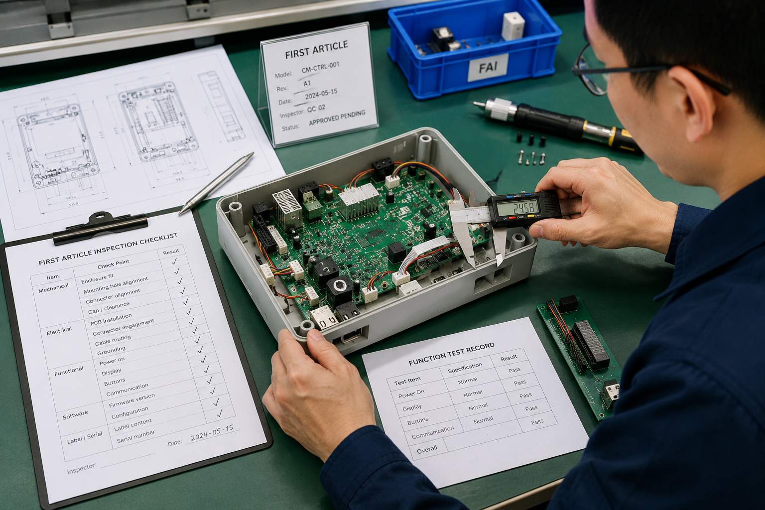
First Article Approval
First article inspection confirms that approved files, materials, programs, equipment settings, and assembly methods produce the intended initial result. Typical checks include polarity, PCBA condition, enclosure fit, connector alignment, firmware version, and initial function.
In-Process Inspection
Use in-process checks for characteristics that may become hidden, including cable routing, internal screws, adhesive position, thermal pads, and connector engagement before closure.
Final Inspection and Testing
Final checks confirm overall function, interface response, enclosure appearance, labels, serial numbers, accessories, and packaging completeness.
Good quality control in electronics manufacturing places each inspection where it provides strong prevention without unnecessary duplication.
4. Define Clear and Measurable Acceptance Criteria
For quality control in electronics manufacturing, an inspection item without a clear acceptance criterion can produce inconsistent decisions.
Instructions such as “appearance must be good,” “function must be normal,” or “screws must be secure” are too vague.
| Requirement Type | Acceptance Criteria Should Define |
|---|---|
| Dimensional | Nominal value, tolerance, measurement point, and tool |
| Functional | Test input, expected response, limit, and pass/fail result |
| Fastening | Screw type, tool setting, sequence, and final condition |
| Cosmetic | Viewing surface, inspection condition, defect limit, and reference sample |
| Software | Approved firmware, configuration, and verification method |
| Packaging | Correct contents, quantity, orientation, protection, and label information |
Instead of “check screws,” the plan could state:
Confirm the approved screw type is installed using the defined tool setting, with no missing screws, damaged bosses, stripped threads, or abnormal enclosure gaps.
Clear criteria make quality control in electronics manufacturing more repeatable and reduce disagreements between engineering, production, quality teams, and customers.
Where electronics workmanship is involved, applicable IPC standards may provide useful references. These references support quality control in electronics manufacturing, but final criteria should still match the product class, customer specification, approved sample, and manufacturing agreement.
5. Select the Appropriate Inspection Method
In quality control in electronics manufacturing, the selected method should reliably detect the defined risk.
Possible methods include:
- Visual inspection
- Dimensional or electrical measurement
- Barcode or software verification
- Trial assembly
- Golden-sample comparison
- Functional test fixtures
- Pull or retention checks
- Fastening verification
- Leak or sealing tests
- Packaging checks
The method must match the requirement. This keeps quality control in electronics manufacturing aligned with the characteristic being verified.
A caliper can verify a molded-part dimension but cannot confirm assembled-product function. A functional test can confirm power-on behavior but may not reveal a trapped cable or cracked screw boss. A visual check may confirm that a serial label is present but not that it matches the programmed identity.
Some CTQs require several methods. A connector interface may need visual alignment, actual plug insertion, and communication testing.
When a result depends heavily on personal judgment, the plan may require a fixture, measurement limit, reference sample, or clearer instruction. Repeatable methods help quality control in electronics manufacturing remain consistent across operators and batches.
Detailed system checks can refer to an approved functional testing in electronics manufacturing procedure instead of repeating the full sequence.
6. Decide Between Sampling and 100% Inspection
In quality control in electronics manufacturing, not every characteristic requires 100% inspection, but not every risk is suitable for sampling.
The inspection level in quality control in electronics manufacturing should consider:
- Product risk
- Customer requirements
- Production volume
- Process stability
- Supplier performance
- Defect history
- Ability to detect the problem later
- Consequences of a missed defect
- Safety or regulatory requirements
Unit-level verification may be appropriate for product configuration, firmware version, serial numbers, critical functions, safety-related connections, and customer-mandated checks.
Sampling may be suitable for stable, lower-risk characteristics such as selected dimensions from a qualified supplier, standard packaging materials, non-critical appearance areas, or features controlled by a proven process.
The plan should not use a fixed percentage simply because it was used on another product.
ANSI/ASQ sampling standards provide structured methods for selecting sample sizes and acceptance criteria. The chosen level should still reflect product risk and customer requirements.
For quality control in electronics manufacturing, the key question is whether an undetected defect could create an unacceptable product, safety, process, or traceability risk.
7. Create a Reaction Plan for Nonconforming Results
Quality control in electronics manufacturing is incomplete if the plan explains how to inspect a product but not what to do when it fails.
In quality control in electronics manufacturing, the reaction plan should define:
- Whether production must stop
- How affected products will be identified
- Where nonconforming units will be isolated
- Whether the inspection scope must expand
- Whether 100% screening is required
- Who reviews the issue
- Whether rework is allowed
- How rework is verified
- Who approves release
- Which documents or processes must be updated
The response should reflect the issue’s severity.
An incorrect firmware version may require identifying affected serial numbers, reprogramming units, repeating tests, and updating records. Connector misalignment found during first article approval may require production to stop while the PCB position, enclosure opening, or assembly method is reviewed.
The reaction plan prevents rushed decisions and ensures failed products do not return to production without verification. This makes quality control in electronics manufacturing responsible for containment as well as detection by identifying affected units, material lots, stages, or batches.
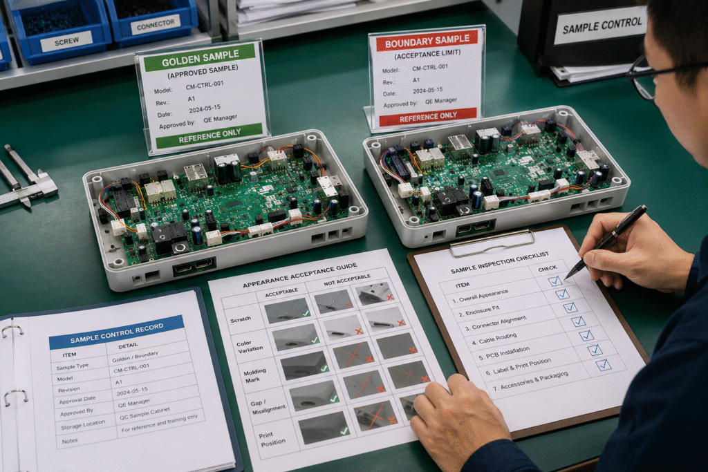
8. Control Golden Samples and Boundary Samples
In quality control in electronics manufacturing, reference samples help communicate cosmetic and assembly requirements when drawings alone are insufficient.
Golden Sample
A golden sample represents the approved condition. It may confirm:
- Appearance
- Enclosure fit
- Button feel
- Display position
- Label placement
- Cable routing
- Assembly configuration
- Packaging arrangement
Boundary Sample
A boundary sample shows the limit between acceptable and unacceptable conditions, such as:
- Maximum acceptable scratch
- Permitted color variation
- Acceptable enclosure gap
- Approved molding mark
- Print-position limit
- Cosmetic defect boundary
Reference samples should be controlled documents. Define:
- Sample identification
- Product revision
- Approval status and date
- Storage and protection
- Responsible department
- Replacement procedure
After any PCB, enclosure, firmware, label, or packaging change, confirm that each reference sample still matches the approved product. Reference sample control keeps quality control in electronics manufacturing aligned with the current revision.
9. Connect the Quality Plan with Revision Control
Quality control in electronics manufacturing must change when the product changes.
Relevant changes may include:
- PCB revisions
- BOM updates
- Approved substitutions
- Connector replacements
- Firmware updates
- Enclosure modifications
- Cable or fastener changes
- Test updates
- Packaging revisions
For every change, ask:
- Does it introduce a new CTQ?
- Is an existing inspection item no longer valid?
- Must acceptance criteria or test methods change?
- Must the golden sample be replaced?
- Do work instructions require revision?
- Are existing materials or finished products affected?
- Is another first article approval required?
An outdated plan can create false confidence while missing the most important change.
The plan should therefore be linked to current drawings, BOMs, firmware files, test specifications, work instructions, approved samples, and inspection records. This linkage keeps quality control in electronics manufacturing aligned with approved technical information.
Detailed material, firmware, and test identification can be managed through traceability in electronics manufacturing.
10. Review the Quality Plan Before Production Release
Before production begins, engineering, production, testing, and quality teams should review the plan together.
Confirm that:
- All CTQs have been identified
- Each important risk has an inspection method
- Inspection stages and responsibilities are assigned
- Acceptance criteria are measurable
- Tools, fixtures, and measurement equipment are available
- Functional tests are validated
- Reference samples are approved
- Inspectors and operators are trained
- Forms use the correct revision
- Inspection levels and reaction plans are clear
A plan may look complete but fail in practice if a dimension becomes inaccessible, a connector is blocked, or a fixture does not support the latest firmware.
A pre-production review ensures that quality control in electronics manufacturing is practical, not merely documented.
Product-Specific Quality Control Plan Template
The following template can be adapted to the product design, production stage, and risk level.
| CTQ Requirement | Inspection Stage | Inspection Method | Acceptance Criteria | Inspection Level | Record | Reaction Plan |
|---|---|---|---|---|---|---|
| PCB and enclosure fit | First article | Trial assembly | Fits without force or interference | First unit and defined sampling | FAI record | Stop and review dimensions |
| Connector alignment | First article and final assembly | Visual check and plug trial | Full insertion without enclosure interference | Risk-based | Assembly record | Isolate and review positioning |
| Firmware version | Programming | Software verification | Matches approved model and revision | 100% where required | Programming log | Isolate and reprogram |
| Cable routing | In-process assembly | Visual and closure check | No pinching, tension, or blocked fasteners | Defined level | Assembly checklist | Rework and inspect affected units |
| Screw fastening | Assembly | Tool and visual verification | Correct screw with no boss damage | Risk-based | Fastening record | Stop and review tool or material |
| Product function | Final testing | Approved test fixture | Meets defined limits and responses | Product-specific | Test report | Isolate failures and investigate |
| Surface appearance | Final inspection | Controlled visual check | Meets approved cosmetic standard | Sampling or defined level | Inspection report | Segregate and review |
| Label and serial number | Final inspection | Visual and scan check | Correct, readable, and traceable | 100% where required | Final record | Relabel and verify |
| Packaging contents | Packing inspection | Checklist and visual check | Correct protection, accessories, and quantity | Defined level | Packing record | Repack and verify |
This table is a framework, not a universal checklist.
Common Mistakes When Building a Quality Control Plan
Using a Generic Checklist
A copied checklist may miss important functions, enclosure features, firmware settings, or customer requirements.
Using Vague Acceptance Criteria
Instructions such as “check fit” or “verify appearance” do not support consistent decisions.
Assigning the Wrong Inspection Stage
Some characteristics are checked after they become hidden, while others are repeated without a clear reason.
Ignoring Firmware and Configuration
The hardware may be correct while the product contains the wrong firmware, model setting, or calibration data.
Failing to Define a Reaction Plan
Inspectors may identify a defect but have no clear instruction for containment, escalation, rework, or release.
Not Updating the Plan After Changes
An outdated inspection document may verify the previous design instead of the current product.
How Cindy Mould Supports Product-Specific Quality Planning
Cindy Mould supports product-specific quality control in electronics manufacturing for projects involving PCB assembly services, plastic enclosures, wiring, connectors, firmware programming, functional testing, final assembly, and packaging.
Depending on the project, the review may cover PCB and enclosure integration, cable arrangement, fastening, firmware configuration, functional tests, appearance, labels, packaging, and traceability records.
A coordinated product assembly service can help identify risks that appear only when the PCBA, enclosure, wiring, firmware, and mechanical components are integrated.
The inspection scope should follow the product design, application, approved technical files, production stage, and customer requirements.
Frequently Asked Questions
What Is a Quality Control Plan in Electronics Manufacturing?
A quality control plan defines what will be inspected, when it will be checked, which method will be used, what result is acceptable, how many units will be inspected, and what action follows a failed result.
It may cover PCBAs, enclosures, cables, firmware, assembly, function, labels, and packaging.
What Should an Electronics Quality Control Plan Include?
It should include CTQs, product risks, inspection stages, methods, acceptance criteria, inspection levels, responsibilities, records, and reaction plans.
Should Every Electronic Product Receive 100% Inspection?
No. The level depends on risk, customer requirements, process stability, volume, and the consequences of a missed defect.
Critical functions, firmware identity, serial numbers, or safety-related requirements may need 100% verification. Stable lower-risk characteristics may be suitable for controlled sampling.
Why Is a Reaction Plan Necessary?
A reaction plan defines what happens after a failed inspection. It helps the team isolate affected products, control production, expand inspection, verify rework, investigate the cause, and approve release.
Conclusion
Effective quality control in electronics manufacturing does not begin with a universal checklist. It begins with the specific product.
Manufacturers should identify critical electrical, mechanical, functional, cosmetic, software, and packaging requirements. Each risk must then be connected to the correct inspection stage, a reliable method, measurable acceptance criteria, an appropriate inspection level, a quality record, and a reaction plan.
Golden samples, revision control, traceability, and pre-production review help keep the plan aligned with the approved design as the project changes.
By building the inspection plan around the actual product, manufacturers can focus quality resources on the characteristics that matter most and identify integration risks before they spread into batch production.
For projects involving PCBA, plastic enclosures, wiring, firmware, testing, and final assembly, you can contact Cindy Mould with your drawings, BOM, test requirements, samples, and production information for an initial project review.