
A plastic enclosure can look simple on the outside and still become difficult to mold and assemble.
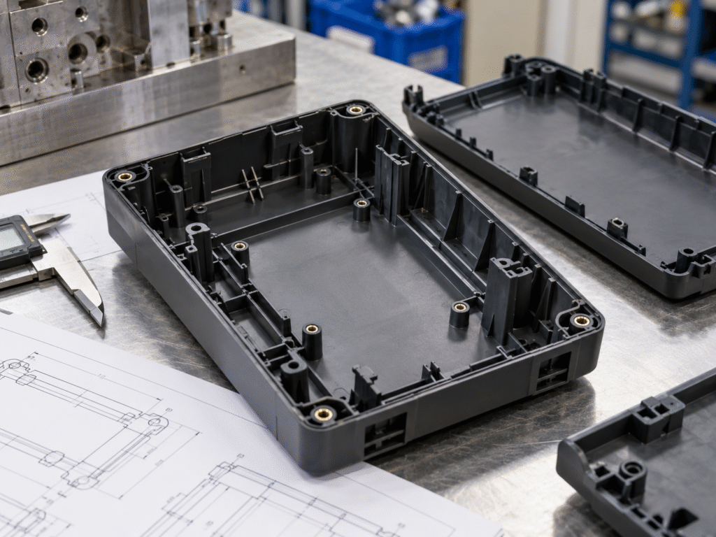
A typical housing may contain only two visible shells, but inside there may be screw bosses, PCB supports, reinforcing ribs, snap hooks, connector openings, button guides, cable channels, and locating features.
Each feature may work well on its own.
Problems often begin when all of them are placed into the same part.
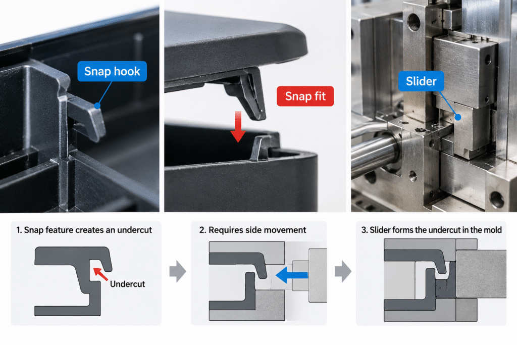
A rib added for stiffness may leave a sink mark on the outer surface. A screw boss may be correctly positioned in CAD but leave no room for a screwdriver during assembly. A snap fit may hold the housing tightly but create an undercut that requires a slider or lifter in the mold.
This is why plastic enclosure design should not be reviewed one feature at a time.
The wall, ribs, bosses, snap fits, cosmetic surfaces, internal components, mold structure, and assembly process all need to work together.
For a new enclosure project, the following design sequence helps identify problems before tooling begins.
1. Start With the Main Wall Before Adding Internal Features
Before adding ribs, bosses, or snap fits, first look at the main enclosure wall.
Wall thickness affects how the cavity fills, how the part cools, how much it shrinks, and how stable the final shape will be.
The first questions are usually simple:
- Is the wall thickness reasonably consistent?
- Are there sudden thick-to-thin transitions?
- Are there long flat walls that may deform?
- Are some flow sections unusually thin?
- Are any thick areas located behind visible cosmetic surfaces?
Uniformity matters because plastic does not cool at the same rate in thick and thin sections.
If one area contains much more material than the surrounding wall, it normally stays hot longer and shrinks differently.
That may appear later as:
- sink marks;
- local deformation;
- warpage;
- dimensional variation;
- longer cooling time.
Thicker does not automatically mean stronger
A common response to a flexible enclosure is simply to make the wall thicker.
That can work in some cases, but it is not always the best solution.
A thicker wall also means more plastic, more cooling, and potentially more shrinkage.
For a large housing, increasing the entire wall thickness to solve one weak area may add material everywhere even though reinforcement is only needed locally.
In many cases, a better approach is to keep the main wall reasonable and use ribs where stiffness is actually required.
There is no single wall thickness that works for every enclosure.
The appropriate value depends on the resin, flow length, part size, geometry, strength requirement, and surface expectation.
The important point is to establish the main wall first.
For additional material-design background, Covestro’s general design guide for thermoplastic parts discusses wall thickness, ribs, bosses, and draft as related design elements rather than isolated features.
Ribs and bosses should then be designed around that wall rather than added independently.
In plastic enclosure design, establishing this wall-thickness baseline first makes later rib, boss, and snap-fit decisions easier to evaluate.
2. Add Ribs Where the Housing Actually Needs Support
Ribs are useful because they can increase stiffness without making the entire plastic wall thicker.
But simply adding more ribs does not automatically produce a better enclosure.
Before adding a rib, it is useful to ask:
What problem is this rib solving?
Common areas that may need reinforcement include:
- long side walls;
- large flat panels;
- PCB support areas;
- regions around screw bosses;
- connector openings;
- button areas;
- mounting points.
For example, a long side wall may flex when the housing is handled.
A rib running in the correct direction can reduce that movement without adding material across the entire wall.
The same logic applies around connectors or mounting areas where local force enters the housing.
Rib direction matters
Ribs should support the actual direction of load or deformation.
For plastic enclosure design, rib layout should follow the real load path rather than simply fill available space inside the housing.
A rib placed in the wrong direction may add material without contributing much stiffness.
This is why rib layout should be reviewed together with how the product will be used, mounted, opened, or assembled.
Check the outside surface after adding a rib
This is one of the most important checks in plastic enclosure design.
After adding internal reinforcement, look at the opposite side of the wall.
If the rib is too thick or creates too much material at its root, the outside surface may show:
- sink marks;
- read-through;
- gloss variation;
- local deformation.
This becomes especially important on customer-facing surfaces.
A rib may be completely hidden inside the product, but the sink mark it creates may be the first thing the customer sees.
The design therefore has to balance three requirements:
stiffness, moldability, and appearance.
3. Add Bosses Only After You Know What They Need to Hold
A screw boss may look like a simple cylindrical feature, but its design depends heavily on its actual function.
Before sizing a boss, first decide what it needs to do.
Is it used for:
- fixing a PCB;
- joining the upper and lower housing;
- receiving a self-tapping screw;
- holding a threaded insert;
- locating an internal component;
- supporting another molded part?
A boss used to hold a PCB does not necessarily need the same structure as one carrying the main housing screws.
Common boss problems we check during DFM
Typical issues include:
- excessively thick boss walls;
- bosses placed too close to the outer surface;
- very tall unsupported bosses;
- insufficient draft;
- poor rib support;
- weak connection to the main wall;
- interference with nearby components.
Making a boss larger is not always the best way to increase strength.
A heavy boss can create a thick local section where it meets the enclosure wall.
That area cools more slowly and can produce a visible sink mark on the opposite side.
A more balanced design may use controlled boss thickness together with reinforcing ribs.
Can the screwdriver actually reach the screw?
This is easy to miss in CAD.
The boss itself may be perfectly positioned, but assembly can still fail if the tool cannot reach it.
Before tooling, it is worth checking:
- Is there enough space above the screw?
- Can the screwdriver approach in a practical direction?
- Does a nearby wall block access?
- Will the PCB or another component cover the screw?
- Is there enough clearance around the screw head?
These are small details during design but important details on an assembly line.
A boss needs to be more than moldable.
It also needs to be assemblable.
Boss design is a good example of why plastic enclosure design has to consider molding and assembly at the same time.
4. Decide Whether the Housing Really Needs Snap Fits
Snap fits are commonly used in plastic enclosures, but they should have a clear purpose.
A snap may be used to:
- position two housing halves before screws are installed;
- reduce screw count;
- retain a cover;
- hold an internal part;
- speed up assembly.
If the function is not clear, adding more snap features may only make the part and mold more complicated.
A snap fit has to work twice
A snap fit has one job during product assembly and another during molding.
During assembly, it has to flex enough to pass the locking feature and then recover sufficiently to hold the parts together.
During molding, the feature still has to release from the tool.
Both conditions need to be checked.
Stronger does not always mean better
A very stiff snap may give high retention force, but it can also create:
- high assembly force;
- difficult operator handling;
- stress at the snap root;
- cracking;
- poor serviceability if the enclosure needs to be reopened.
A snap that is too flexible creates a different problem.
The housing may feel loose, gaps may increase, or the locking feature may not hold reliably.
The target is not maximum stiffness.
It is enough retention force for the actual product requirement.
For engineers evaluating snap behavior, SABIC also provides engineering tools for snap-fit feasibility, including insertion and pullout-force calculations.
Snap direction can change the mold structure
Snap geometry also affects tooling.
A side-facing hook may create an undercut that cannot release in the normal mold-opening direction.
The mold designer then has to decide whether the feature can be:
- redirected;
- simplified;
- released through controlled plastic flexing;
- formed by a lifter;
- formed by a slider.
A small change in snap direction can sometimes eliminate a complete side action.
That affects mold size, machining, moving components, maintenance, and injection mold cost.
For plastic enclosure design, snap direction should be reviewed before tooling because one small undercut can change the mold structure.
5. Check the Outside Surface After Adding the Inside Structure
Once ribs, bosses, snap fits, and locating features have been added, stop looking only at the inside of the enclosure.
Turn the model around and inspect the cosmetic surfaces again.
Internal features often affect the outside more than expected.
Internal features can appear on the outside
Common symptoms include:
- sink marks above screw bosses;
- visible rib read-through;
- local gloss differences;
- distortion around thick sections;
- uneven surfaces near internal reinforcement.
This is particularly important for front covers, handheld products, control panels, and visible equipment housings.
From the customer’s point of view, it does not matter that the internal structure is strong if the outer surface shows obvious molding defects.
This creates an important trade-off.
A boss may need more support.
A rib may need more stiffness.
But every increase in local material can also increase cosmetic risk.
Good plastic enclosure design usually comes from balancing these requirements rather than maximizing any single feature.
For appearance-critical housings, plastic enclosure design should always be reviewed from both the inside structure and the visible outside surface.
6. Check Whether the Housing Can Actually Be Assembled
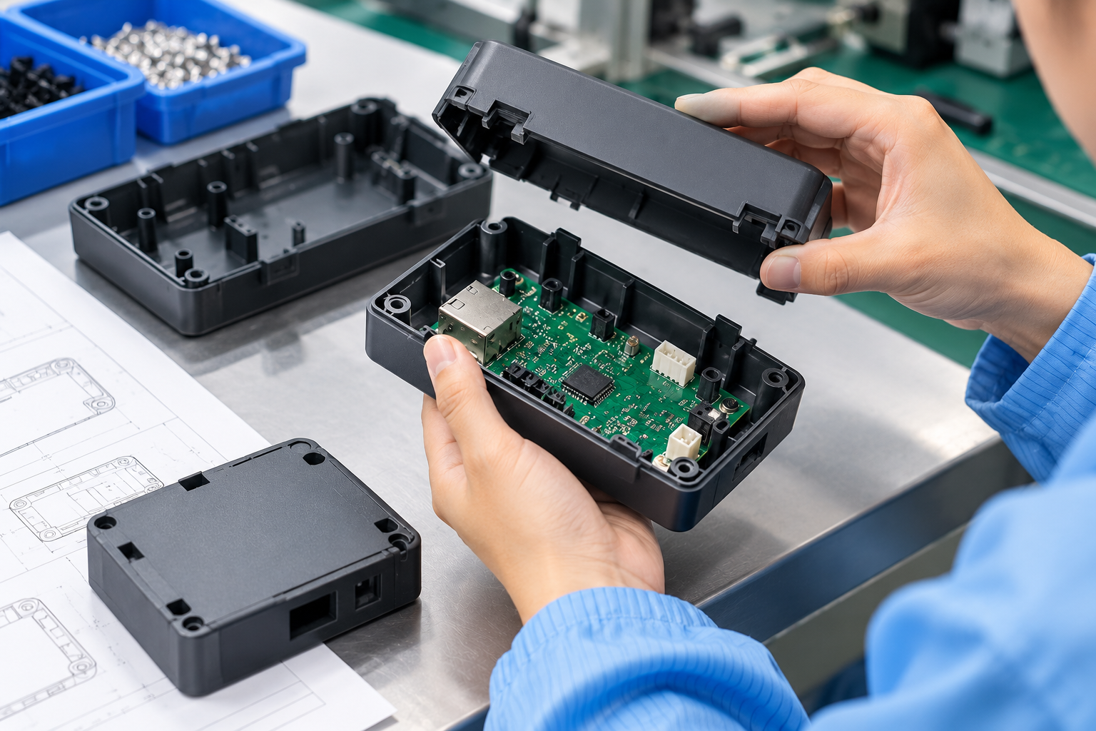
A plastic housing should not be reviewed as an isolated molded part if it will later contain electronics or mechanical components.
The full assembly matters.
Typical interfaces include:
- PCB positions;
- connectors;
- buttons;
- displays;
- cables;
- antennas;
- sensors;
- batteries;
- screws;
- secondary plastic parts.
A plastic part can pass dimensional inspection and still create trouble during final assembly.
Connector openings
A connector opening may look correct in the enclosure CAD.
But the real position of the connector depends on:
- PCB location;
- PCB tolerance;
- boss position;
- housing shrinkage;
- assembly clearance.
A small accumulated shift may cause the connector to sit too high, too low, or too far from the opening.
The plastic housing itself may still appear acceptable.
The assembled product does not.
PCB locating bosses
One boss may be within tolerance.
Several bosses together can create a different problem.
If their positions accumulate in the wrong direction, the PCB may become difficult to install or may sit under stress.
This is why critical dimensions should be reviewed as an assembly system, not only as individual measurements.
Button structures
Buttons are another common example.
The external button may look correctly positioned while the internal guide does not align with the PCB switch.
The result can be:
- inconsistent button feel;
- excessive travel;
- off-center actuation;
- sticking.
Screw access
Even when every component fits, the assembly sequence still needs to make sense.
If one component blocks access to a screw that must be installed later, the assembly order may need to change.
This is why final assembly information is valuable during DFM.
Problems that look minor in a plastic part can become much more expensive after the product reaches assembly.
This assembly-level review is an important part of plastic enclosure design, especially when the housing contains PCBs, connectors, buttons, displays, or other internal components.
7. Check What the Mold Has to Do to Release the Part
Once the enclosure works structurally and in assembly, the next question is:
How will the mold release it?
This review normally includes:
- draft;
- undercuts;
- parting line;
- sliders;
- lifters;
- shut-offs;
- ejection.
A CAD model may look complete while still containing features that lock the part into the mold.
Small features can change the entire mold structure
Common examples include:
- side snap hooks;
- recessed clips;
- side openings;
- deep internal hooks;
- locking features.
These details may occupy only a small area of the part, but they can require a much larger tooling change.
A straightforward two-plate mold may become a slider or lifter mold because of one small side feature.
That does not mean every such feature must be removed.
Some features are necessary for product function.
The purpose of DFM is to identify which complexity is necessary and which complexity can be avoided.
Draft also needs to be checked after the internal design is complete
Draft is often considered early, but ribs, bosses, and inner walls added later can create new vertical surfaces.
Those features still need to release.
Textured surfaces may need additional attention because texture increases resistance during ejection.
The final enclosure should therefore be reviewed as a complete moldable shape, not only as the original outer shell.
A complete plastic enclosure design review should therefore include not only product function, but also how the finished part will release from the mold.
8. Run a Final Plastic Enclosure DFM Review Before Tooling
Before releasing the enclosure for mold manufacturing, it is useful to review the complete part one more time.
12 Things to Check Before Releasing a Plastic Enclosure for Tooling
- Is the main wall thickness reasonably consistent?
- Are thick-to-thin transitions gradual enough to avoid large cooling differences?
- Are ribs placed where the housing actually needs reinforcement?
- Could ribs or bosses create sink marks on visible surfaces?
- Are screw bosses properly supported without creating unnecessary material buildup?
- Can assembly tools reach all screws and fasteners?
- Do snap fits have enough flexibility for practical assembly?
- Do any snap fits, clips, or side openings create undercuts?
- Is sufficient draft provided on walls, ribs, bosses, and textured surfaces?
- Do PCB, connector, display, button, and other component positions align with the housing?
- Are important cosmetic areas protected from unwanted gate marks, ejector marks, sink, or visible parting-line issues?
- Are the dimensions that truly affect assembly and product function clearly identified?
The purpose of this checklist is not to make every enclosure follow the same design rules.
It is to make sure the major interactions have been reviewed before steel is cut.
This final DFM check helps confirm that the plastic enclosure design is ready for tooling rather than only complete in CAD.
A practical plastic enclosure design review connects these checks instead of treating wall thickness, ribs, bosses, and snap fits as separate decisions.
9. Common Trade-Offs in Plastic Enclosure Design
Many enclosure decisions involve a trade-off.
There is rarely one feature that can be optimized without affecting something else.
| Design Decision | Possible Benefit | Possible Risk |
|---|---|---|
| Thicker wall | Increased local stiffness | Longer cooling, shrinkage, sink or warpage |
| Thicker rib | More local reinforcement | Sink marks or read-through |
| Larger boss | More screw support | Thick section and cosmetic sink |
| Stronger snap fit | Higher retention force | More assembly force or cracking risk |
| Tighter tolerance | Better control of critical fit | More tooling adjustment and inspection |
| Hidden gate position | Better visible appearance | More difficult cavity filling |
| More undercut features | Greater design freedom | More complex mold structure |
This is why a design rule should not be applied without considering the rest of the product.
A thicker rib may solve one problem and create another.
A stronger snap may improve retention but make assembly harder.
A tighter tolerance may improve one interface while increasing mold adjustment for a dimension that has little effect on product performance.
The best decision is usually the one that gives enough performance without creating unnecessary manufacturing complexity.
That balance is at the center of practical plastic enclosure design: enough strength, fit, and appearance without adding avoidable tooling or assembly difficulty.
10. What Information Should Be Ready Before Tooling Starts?
A plastic enclosure review is much more useful when the tooling team can see how the part fits into the complete product.
For a new project, useful information includes:
- 3D CAD files;
- 2D drawings, if available;
- plastic material;
- surface finish or texture;
- cosmetic surface requirements;
- critical dimensions;
- PCB or internal component files;
- assembly drawings;
- expected annual production volume;
- product usage requirements.
If the enclosure will contain electronics, sharing only the plastic housing file may not show the complete picture.
The PCB, connectors, buttons, display, cables, and other components help explain which dimensions really matter.
For example, a screw boss may appear correct when looking only at the housing.
Once the PCB is added, it may become clear that the boss interferes with a component or places the board too close to the housing wall.
The earlier this is discovered, the easier it is to correct.
For plastic enclosure design, providing the assembly context before tooling starts helps the engineering team identify which interfaces and dimensions deserve the closest attention.
The more complete the project information is, the more accurately the plastic enclosure design can be reviewed before mold manufacturing begins.
Conclusion: A Good Enclosure Must Work in the Mold and on the Assembly Line
Good plastic enclosure design is not simply about creating a housing that can be injection molded.
The part also needs to survive the rest of the manufacturing process.
It has to fill and cool predictably in the mold.
It has to release without unnecessary tooling complexity.
Its internal ribs and bosses should provide enough structural support without creating visible sink marks.
Its snap fits should hold reliably without making assembly unnecessarily difficult.
And once the plastic part is molded, the PCB, connectors, buttons, display, cables, screws, and other components still have to fit correctly.
That is why enclosure development is best viewed as one connected process:
DFM → Mold Design → Injection Molding → Product Assembly
Reviewing the complete product before tooling begins does not eliminate every adjustment at T1.
It does, however, help identify problems while they are still relatively easy to change in CAD instead of after the mold has been manufactured.
At CINDY MOULD, we support plastic enclosure projects from DFM and mold design through injection molding and final product assembly.
If you are preparing a new plastic enclosure for tooling, sharing the housing CAD together with material, cosmetic, production, and assembly information can help us review potential molding and fit issues before mold manufacturing begins.
FAQ
What wall thickness should a plastic enclosure use?
There is no single wall thickness that is correct for every plastic enclosure. The suitable thickness depends on the resin, part size, flow length, required stiffness, geometry, cosmetic requirements, and molding conditions. Consistency across the part is often as important as the nominal thickness itself.
How can ribs strengthen a plastic enclosure without causing sink marks?
Ribs should be placed where reinforcement is actually needed and sized in relation to the surrounding wall. Excessively thick ribs can create local material buildup and visible sink marks on the opposite surface, so rib strength and cosmetic requirements need to be reviewed together.
Why do screw bosses sometimes leave marks on the outside of a housing?
A boss creates additional plastic thickness where it meets the main wall. If too much material is concentrated in that area, it cools and shrinks differently from the surrounding wall, which can produce a visible sink mark or read-through on the outer surface.
Can snap fits make an injection mold more complex?
Yes. A snap feature that creates an undercut may require a slider, lifter, flexible release, or another mold action. Reviewing the snap direction during DFM can sometimes simplify the mold without changing the intended assembly function. This is why snap-fit direction is an important plastic enclosure design decision before tooling begins.