
A PCB may pass its electrical checks, and a plastic enclosure may meet its drawing dimensions. Connectors, wires, screws, and other components may also match the approved bill of materials. However, problems can still appear when these parts are combined into one complete product.
The PCB may not align naturally with the mounting bosses. A connector may sit outside the enclosure opening. A wire may become trapped when the housing is closed. A tall component may interfere with an internal rib, while test points that were accessible on the bare PCBA may become blocked after the battery, display, or enclosure is installed.
These are often integration problems rather than individual component defects. A practical design for assembly checklist helps product teams identify them before tooling release or mass production. The objective is not simply to prove that one engineering sample can be assembled. The design should support correct, repeatable, testable, and efficient assembly under real production conditions.
This guide provides a design for assembly checklist covering 12 critical reviews for electronic products.
What Is Design for Assembly in Electronic Product Development?
Design for Assembly, commonly shortened to DFA, is the practice of considering how parts will be positioned, connected, fastened, tested, inspected, and removed while the product is still being designed.
For electronic products, a design for assembly checklist should cover the interaction between:
- The PCB and plastic enclosure
- Components and internal mechanical structures
- Connectors and external openings
- Wires and cable-routing features
- Screws, snap-fits, adhesives, and mounting bosses
- Firmware programming and functional testing
- Rework, maintenance, and disassembly
A good assembly design reduces manual adjustment. Parts should naturally locate in the correct position, installation directions should be clear, and critical operations should not depend entirely on operator experience.
Design for Manufacturing vs Design for Assembly
Design for Manufacturing focuses on whether individual parts can be produced reliably. It considers PCB fabrication, component placement, soldering, moldability, plastic wall thickness, ribs, bosses, draft angles, and other production requirements.
Design for Assembly focuses on what happens after those parts have been manufactured. It asks whether the PCB fits the enclosure, whether mounting holes align, whether connectors are accessible, whether tools can reach every fastener, and whether testing can be completed without unnecessary disassembly.
For additional industry context, see IPC’s guidance on DFM, DFT, and DFA. A design for assembly checklist supports a coordinated review by connecting PCB layout, enclosure design, tooling, testing, and final assembly.
A part can be easy to manufacture but difficult to integrate into the final product. For this reason, PCB layout, enclosure design, testing, and assembly planning should not be developed separately.
Why Is a Design for Assembly Checklist Important?
A successful prototype does not automatically mean that a product is ready for production.
Engineering samples are often assembled by people who already understand the product. They may know that a wire must be moved to one side, one screw must be tightened before another, or the PCB must be inserted at a particular angle.
These adjustments may be acceptable during an early prototype build, but they create risk when the process must be repeated across multiple units and operators. A design for assembly checklist helps distinguish a workable prototype from a design that is truly ready for repeatable assembly.
Warning signs include:
- Pressing the PCB into position
- Pulling wires away from screw bosses
- Holding several loose parts simultaneously
- Reopening the enclosure to correct a connection
- Tightening screws in an undocumented sequence
- Moving a connector until it aligns with an opening
- Bending a component or cable to create clearance
Many assembly problems also occur between parts rather than within a single component. PCB mounting holes interact with plastic bosses, connectors interact with enclosure openings, and wire routes interact with screws, clips, batteries, and test points.
A complete review should therefore examine the whole product rather than the PCB or enclosure alone. This is especially important for projects that combine PCB assembly, molded housings, internal wiring, testing, and final product integration.
Design for Assembly Checklist for Electronic Products
The following design for assembly checklist covers the main areas that should be reviewed before an electronic product enters prototype assembly, pilot production, or mass production.
1. Review Whether Every Component Is Necessary
Begin by reviewing the total number of parts in the assembly.
Every bracket, spacer, washer, screw, tape, gasket, cable clip, or separate plastic piece must be purchased, identified, stored, handled, and installed. Additional parts increase assembly steps and create more opportunities for missing or incorrect components.
Questions to consider include:
- Can a separate bracket be integrated into the enclosure?
- Can a molded locating feature replace a loose spacer?
- Are multiple small parts performing the same function?
- Can certain components be prepared as a subassembly?
- Are any parts easy to omit or install incorrectly?
- Can fastener variation be reduced?
A design for assembly checklist should not treat the lowest possible part count as the only goal. Separate gaskets, inserts, covers, thermal pads, or serviceable modules may still be required for sealing, strength, thermal control, safety, or maintenance.
Each part should be evaluated according to the function it provides and the complexity it adds.
2. Check PCB Outline and Enclosure Clearance
The PCB must fit inside the enclosure under real manufacturing conditions, not only in a nominal CAD model. This is one of the most important clearance checks in electronic product development.
Review:
- Clearance between the PCB edge and enclosure walls
- PCB thickness and support height
- Space above tall components
- Space below solder joints and through-hole leads
- The PCB insertion and removal path
- Clearance around batteries, heat sinks, shields, and antennas
- PCB, component, and plastic-part tolerances
A PCB may fit correctly in its final position but still be difficult to install. It may need to pass a rib, snap-fit, connector, or internal wall before reaching its mounting location.
A small nominal gap may disappear when PCB routing variation, plastic shrinkage, component height, enclosure warpage, and fastening forces combine. Practical validation should include 3D interference analysis, tolerance review, and trial assembly with physical parts.
For products using molded housings, electronic enclosure manufacturing should be coordinated with PCB position, connector openings, mounting structures, and final assembly requirements.
3. Verify Mounting Holes, Bosses, and Locating Features
Within the design for assembly checklist, PCB mounting holes, supports, locating pins, and plastic bosses should be reviewed as one positioning system.
Review:
- Mounting-hole center positions
- Hole diameter and screw clearance
- Locating-pin diameter and height
- Screw-boss wall thickness
- PCB support height
- Distance from bosses to components and solder joints
- The number and distribution of support points
The PCB should rest naturally on its supports without being bent or pulled into position.
One warning sign is an assembly that works only when one specific screw is tightened first. This may indicate insufficient hole clearance, uneven support height, locating errors, or tolerance accumulation.
Screws should secure the assembly after the parts have been positioned correctly. They should not be used to force misaligned parts together.
A physical trial should include installing and removing the PCB several times. Check whether it returns to the same position, whether the holes align without pressure, and whether the board remains level after fastening.
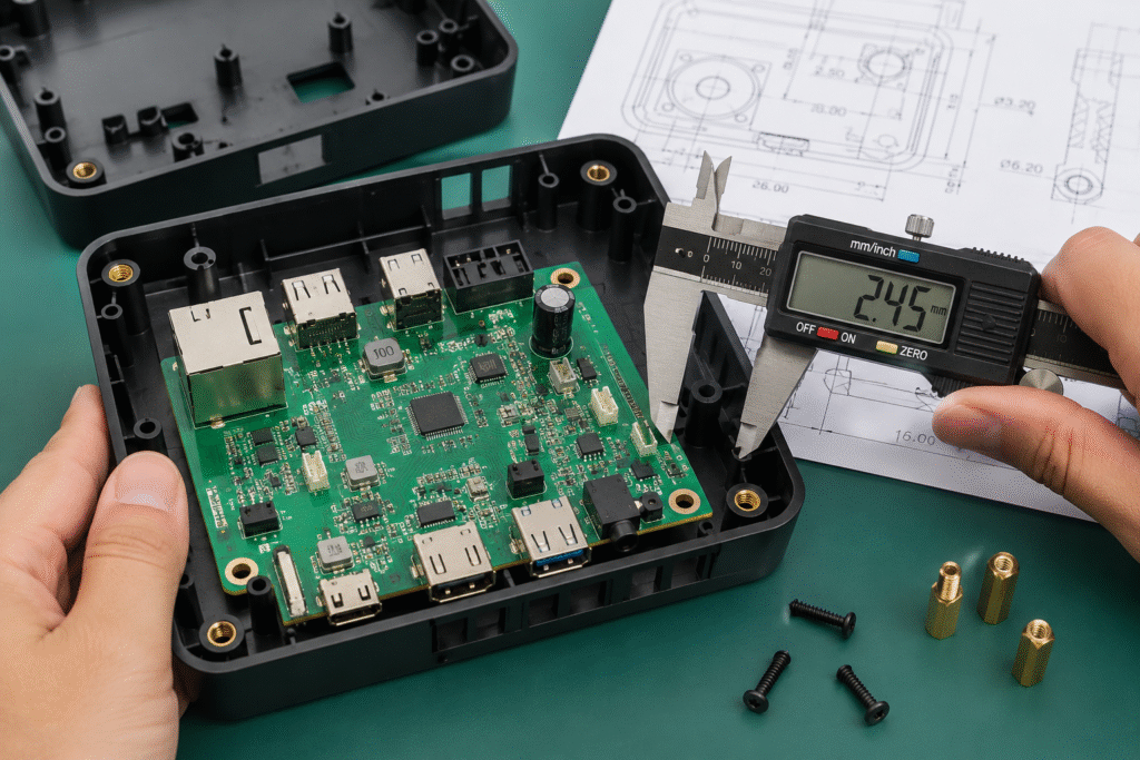
4. Confirm Connector and Enclosure Opening Alignment
External connectors must align with their enclosure openings while allowing normal cable insertion and removal. The design for assembly checklist should confirm connector fit with real mating hardware.
This review may include:
- USB connectors
- Power sockets
- RJ45 interfaces
- Audio connectors
- Antenna connectors
- Memory-card slots
- Buttons and switches
- LEDs and light guides
- Displays, cameras, and sensors
Do not review only the center position of the connector. Enclosure wall thickness, opening size, corner radius, plug overmold, insertion depth, and access angle can all affect usability.
A connector may look correctly aligned in CAD but still be difficult to use with the actual mating plug. The plug housing may contact the enclosure before full insertion, or the opening may provide insufficient space for removal.
Connector support should also be checked. Repeated insertion forces should not place uncontrolled stress on the PCB or solder joints.
Validation should use the intended cable, plug, or accessory rather than inspection of the empty opening alone.
5. Review Component Height and Mechanical Keep-Out Areas
PCB components and internal enclosure structures must have clearly defined keep-out areas. The design for assembly checklist should compare component heights with every nearby enclosure feature.
Components that commonly require additional clearance include:
- Electrolytic capacitors
- Transformers and inductors
- Heat sinks
- Batteries
- Board-to-board connectors
- Shielding covers
- Relays
- Displays and electronic modules
Potential enclosure interference may come from ribs, screw bosses, snap-fits, button mechanisms, light-guide supports, battery holders, cable channels, and upper-cover reinforcement features.
Mechanical restrictions should be communicated during PCB layout, not only after the board design is complete.
The review should consider actual component dimensions, solder height, placement variation, plastic warpage, and enclosure compression during fastening. It should also confirm that ribs, bosses, or other structures do not contact exposed leads, solder joints, or conductive surfaces.
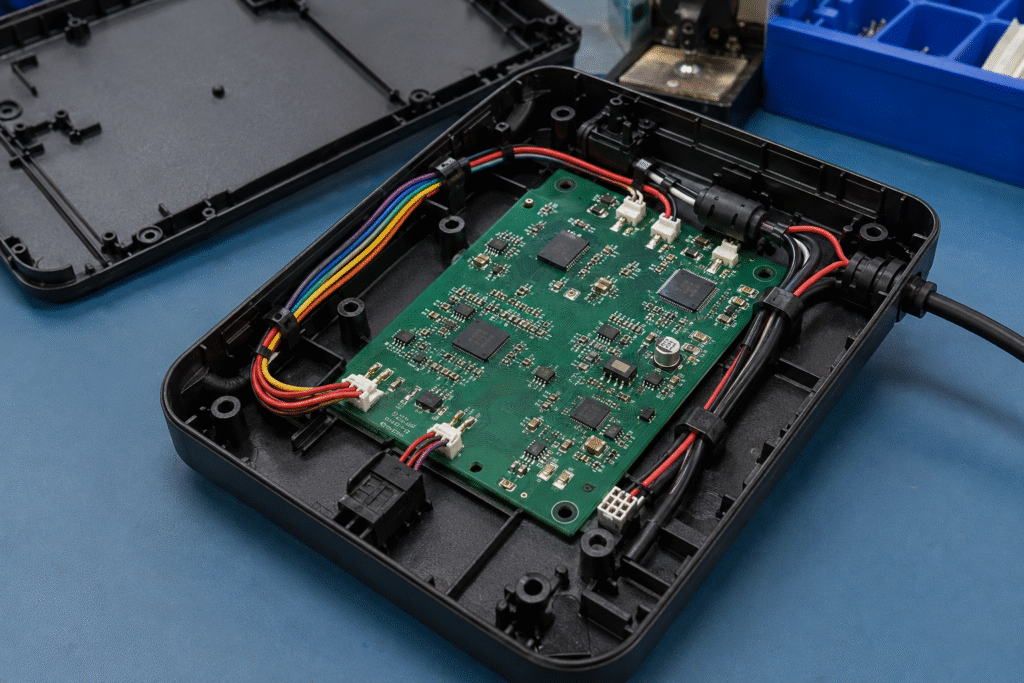
6. Plan Cable Routing, Length, and Bend Radius
Internal wiring should follow a defined route rather than being arranged differently by each operator.
The design for assembly checklist should review:
- Cable length
- Connector orientation
- Bend radius
- Distance from sharp edges
- Clearance from screws and snap-fits
- Distance from hot components
- Cable retention and strain relief
- Wire-crossing points
- Access to fasteners and test points
A cable that is too short may pull on the connector. A cable that is too long may form loops, block screw holes, cover test points, or become trapped when the enclosure is closed.
Cable channels, retaining clips, sleeves, tapes, foam pads, or cable ties may be used where appropriate. The selected method should hold the wiring in a repeatable position without damaging insulation or creating excessive tension.
A clear warning sign is a product that can only be closed after the operator manually pushes each wire into a temporary position. During trial assembly, close the housing slowly and inspect whether any cable moves toward a seam, boss, screw, or snap-fit.
7. Add Error-Proofing and Orientation Features
A good assembly design should make incorrect installation difficult or immediately visible. Error-proofing is therefore a core part of assembly design.
Useful features may include:
- Asymmetrical locating points
- Keyed connectors
- Different connector sizes
- Different pin counts
- One-direction component geometry
- Color identification
- Clear PCB silkscreen
- Cable labels
- Left- and right-hand part markings
For additional guidance on Poka-Yoke, see ASQ’s mistake-proofing resource.
Review whether operators can reverse a connector, exchange two similar cables, rotate a bracket incorrectly, or use the wrong screw.
Structural prevention is generally stronger than relying only on labels and instructions. Work instructions remain important, but the product itself should guide the operator toward the correct action.
8. Simplify the Assembly Sequence
The order in which components are installed affects assembly time, product quality, and rework risk. Use the design for assembly checklist to review the complete sequence, not just the final product.
Ask:
- Does the product need to be turned over repeatedly?
- Does one component block access to another?
- Must any part be installed and removed again?
- Does the operator need to hold several loose parts at once?
- Are connectors installed before they become inaccessible?
- Can screws be tightened from a consistent direction?
- Does a later step place stress on an installed component?
A logical assembly sequence should move from stable internal positioning toward final enclosure closure. Each operation should leave the product in a controlled condition for the next step.
Recording a prototype assembly is a practical way to identify unnecessary movements, pauses, tool changes, repeated adjustments, and difficult operations.
If experienced engineers assemble the same product in different ways, the process may require clearer sequencing, improved locating structures, or more complete work instructions.
9. Review Screws, Snap-Fits, and Adhesive Joining
Joining methods should be evaluated because they affect assembly force, tool access, product appearance, sealing, and serviceability.
Screw Fastening
Check screw diameter, length, tool direction, thread engagement, tightening sequence, torque requirements, and plastic-boss structure.
Avoid using several visually similar screw lengths unless they are necessary. Incorrect screws can damage bosses, contact internal components, or provide insufficient engagement.
Torque should be defined according to the screw, plastic material, boss design, and product requirements. Excessive torque can strip threads or crack plastic, while insufficient torque can leave the enclosure loose.
Snap-Fit Assembly
Check insertion direction, required deflection, engagement confirmation, mold-release requirements, and expected disassembly cycles.
A snap-fit designed for one-time closure may not be suitable for a serviceable product.
Adhesive Assembly
Review adhesive compatibility, application area, dispensing access, quantity, curing conditions, overflow risk, and rework requirements.
No joining method is automatically best. The selection should match the required strength, sealing, appearance, production volume, and maintenance strategy.
10. Check Tool, Fixture, and Operator Access
A position visible in CAD is not necessarily reachable during production. The design for assembly checklist should therefore include access for both operators and intended production tools.
Review access to:
- Screws
- Cable connectors
- Small brackets
- Adhesive locations
- Thermal pads
- Labels
- Test points
- Inspection areas
A screwdriver should reach the screw without contacting nearby components or entering at an uncontrolled angle. Connectors should provide enough finger or tool clearance for complete engagement.
The actual production tool must also be considered. A space that can be reached with a small engineering screwdriver may not accommodate a controlled electric screwdriver or assembly fixture.
Access should be checked after surrounding components have been installed. Physical operator trials can reveal excessive force, difficult wrist positions, visual obstruction, and repeated attempts that are not visible in CAD.
11. Reserve Access for Programming, Testing, and Inspection
Programming and testing requirements should be defined before the PCB and enclosure designs are finalized. A complete design for assembly checklist must include Design for Test considerations.
Review:
- Firmware-programming interfaces
- Test-point position and size
- Probe access direction
- Power and communication connections
- Test-fixture clearance
- Button, display, and LED visibility
- Whether testing occurs before or after enclosure assembly
- Access for fault diagnosis and rework
A test point accessible on the bare PCBA may become blocked by a battery, cable, shield, display, or housing.
The test plan should define which checks are completed at board level and which are completed after final assembly. Board-level testing can identify electronic problems early, while final functional testing for electronic products confirms that the PCB, wiring, firmware, user interfaces, and mechanical assembly operate together.
Testing access designed into the product can reduce complicated manual connections, repeated disassembly, and unnecessary fixture complexity.
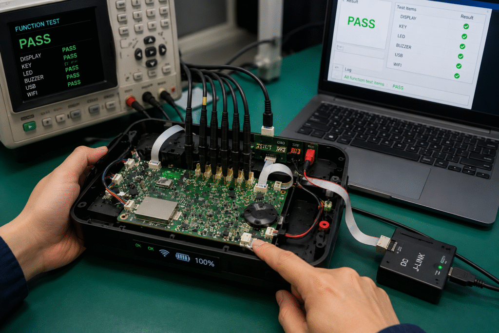
12. Consider Rework, Service, and Disassembly
The final review should address how the product will be opened, repaired, and reassembled when required.
Review:
- Whether the enclosure can be opened without damage
- Whether snap-fits can be released safely
- Whether screws remain accessible
- Whether the PCB and battery can be removed
- Whether cables can be disconnected without damage
- Whether adhesive blocks access to critical components
- Whether sealing performance can be restored
- Whether cosmetic surfaces are protected during rework
Permanent joining may be appropriate for sealed, disposable, or safety-critical products. Equipment that requires field service may need a different approach.
A disassembly trial is useful even when the product is not intended for customer repair. Manufacturing teams may still need to open units for failure analysis, component replacement, programming correction, or process verification.
Reassembly should also restore the required fit, appearance, fastening condition, and sealing performance.
Common Design for Assembly Mistakes
A design for assembly checklist is especially useful for identifying recurring mistakes before they become production issues.
Designing the PCB and Enclosure Separately
Without regular coordination, connector positions, mounting holes, component heights, and mechanical keep-out areas may become inconsistent.
Checking Only Nominal Dimensions
Production parts vary within their tolerances. A nominal gap is not enough when combined dimensional variation can create interference or poor alignment.
Depending on Manual Adjustment
Bending a wire, pushing a PCB, or applying force to close the enclosure should be treated as a design warning rather than a permanent production method.
Using Too Many Similar Fasteners
Similar screws can be mixed during assembly, causing damaged bosses, inadequate engagement, or contact with internal components.
Leaving Cable Routing to the Operator
Undefined cable paths create variation in enclosure closure, connector stress, airflow, testing access, and final appearance.
Reviewing Test Access Too Late
Programming and test requirements added after PCB or tooling release may require complicated fixtures, disassembly, or design changes.
How to Validate a Design for Assembly Checklist Before Mass Production
A design for assembly checklist is most effective when combined with physical and process validation.
Conduct a Cross-Functional 3D Review
The electronic, mechanical, PCB assembly, injection molding, testing, quality, and final assembly teams should review the complete product together.
The review should cover clearance, PCB insertion paths, tool access, cable routing, connector alignment, testing access, fastening, and disassembly.
Comments should be connected to the relevant PCB revision, drawing, BOM item, test specification, or process document.
Build and Document an Engineering Prototype
The prototype should be evaluated for more than function. Use the design for assembly checklist to record the assembly sequence, difficult insertions, wire positioning, connector engagement, screw access, housing gaps, testing access, and disassembly process.
Where possible, use the intended production parts and tools. A sample assembled with temporary components or special engineering tools may not reveal the same production risks.
Run a Small-Batch Pilot Assembly
A pilot build helps confirm whether the design for assembly checklist has addressed repeatability across several units and operators.
Observe whether operators follow the same sequence, which operations cause repeated difficulty, whether parts can be installed incorrectly, and whether dedicated fixtures are required.
Products that combine PCBA, molded housings, wiring, connectors, and modules can also benefit from a controlled product assembly process before full production release.
Close Issues Through Controlled Revisions
Assembly improvements should be updated in the PCB layout, 3D models, mechanical drawings, cable drawings, BOM, work instructions, test specifications, and inspection criteria.
Correcting one sample without updating the approved documents does not fully resolve the production risk.
Design for Assembly Checklist Summary
The table below summarizes the key review areas in this design for assembly checklist.
| Review Area | Key Question | Typical Risk | Validation Method |
|---|---|---|---|
| Component Count | Is every component necessary? | Extra steps and missing parts | BOM and structure review |
| PCB Clearance | Is clearance sufficient across tolerances? | Interference or forced assembly | 3D analysis and sample check |
| Mounting Features | Are holes, bosses, and supports aligned? | PCB stress or boss damage | Fit and fastening trial |
| Connectors | Do connectors align with actual mating plugs? | Incomplete insertion or stress | Cable and plug testing |
| Component Height | Are mechanical keep-out areas respected? | Cover or rib interference | Height review and closure test |
| Cable Routing | Are wires guided and protected? | Pinching, tension, or blocked access | Trial assembly |
| Error-Proofing | Can parts be installed incorrectly? | Reversed or mixed components | Poka-Yoke review |
| Assembly Sequence | Is the process logical and repeatable? | Rework and operator variation | Recorded assembly trial |
| Joining Methods | Are fasteners and adhesives controlled? | Loose joints or damaged plastic | Torque and fit validation |
| Tool Access | Can production tools reach each location? | Incomplete or angled assembly | Operator and tool trial |
| Testing Access | Are programming and test points accessible? | Complex fixtures or disassembly | Test-fixture review |
| Rework | Can the unit be opened safely if required? | Housing damage or lost sealing | Disassembly trial |
When Should the Design for Assembly Checklist Be Reviewed?
The design for assembly checklist should be used at several product-development stages:
- After the initial mechanical layout
- After the PCB placement is mostly defined
- Before injection mold tooling
- After engineering prototype assembly
- During pilot production
- After major design or BOM changes
Changes to a connector, battery, cable, fastener, PCB revision, or testing requirement can affect enclosure fit, tool access, assembly sequence, and functional validation.
The design for assembly checklist should therefore be repeated whenever a change influences the way parts interact.
How Cindy Mould Supports Electronic Product Assembly
Cindy Mould supports projects that combine plastic enclosures, PCBAs, wiring, connectors, modules, firmware programming, functional testing, labeling, packaging, and final product integration.
Our product assembly services can include a design for assembly checklist covering PCB and enclosure fit, connector alignment, wire routing, fastening, test access, prototype assembly, pilot builds, and final functional checks.
Coordinating electronic and mechanical manufacturing within one project can help identify cross-component problems that may not be visible when each part is reviewed independently. The exact review scope depends on the product design, technical files, production stage, and customer requirements.
Frequently Asked Questions
What Is Included in a Design for Assembly Checklist?
A design for assembly checklist normally covers component count, PCB clearance, mounting features, connectors, component height, cable routing, error-proofing, fastening, tool access, testing access, assembly sequence, and rework requirements.
When Should a Design for Assembly Checklist Be Reviewed?
A design for assembly checklist should begin during PCB and mechanical design. It should be reviewed again before tooling, after prototype assembly, during pilot production, and after major design changes.
What Is the Difference Between DFM and DFA?
DFM evaluates whether individual parts can be manufactured reliably. DFA evaluates whether those parts can be positioned, connected, fastened, tested, and inspected efficiently as a complete product. A design for assembly checklist converts these DFA requirements into practical review steps.
Why Can a Prototype Work but Still Create Production Problems?
Prototype assembly may depend on engineering experience, manual wire adjustment, a special fastening sequence, or repeated repositioning. A design for assembly checklist helps reveal which of these actions may become inconsistent during repeated production.
Should Testing Access Be Included in a Design for Assembly Checklist?
Yes. A design for assembly checklist should include programming interfaces, test points, functional connections, indicators, and fixture access before the PCB and enclosure designs are finalized.
Conclusion
A practical design for assembly checklist does more than confirm that individual components fit together.
It checks whether parts locate naturally, PCB and enclosure clearances remain acceptable across tolerances, connectors align with real mating plugs, wiring follows a controlled route, and fasteners can be installed consistently.
It also verifies that operators, tools, test fixtures, and inspection equipment can access the required locations without repeated adjustment or disassembly.
Using the design for assembly checklist throughout electronic, mechanical, testing, and production development can identify avoidable risks earlier and support a more stable transition from prototype assembly to repeatable production.
For projects involving PCBA, plastic housings, wiring, testing, and complete product integration, you can contact Cindy Mould with your drawings, BOM, PCB files, samples, and assembly requirements for an initial review.