
Injection Molding Parting Line: What It Is and Why It Matters
When reviewing a plastic part for injection molding, attention often goes first to wall thickness, draft, ribs, bosses, and undercuts. But another decision can have a significant influence on both the mold and the finished part:
Where should the mold separate?
That decision defines the parting line.
On the finished plastic part, an injection molding parting line may appear as a thin line around an edge or across a surface. It can look like a minor cosmetic detail, but its location is closely connected to mold opening direction, tooling structure, flash control, dimensional consistency, and downstream assembly.
For a simple plastic cover, the parting line may follow the outer edge with little difficulty. For a more complex housing with openings, snap hooks, textured surfaces, and internal features, choosing the parting line can involve several engineering trade-offs.
That is why parting line location should be considered during DFM and mold design, not after mold manufacturing has already started.
What Is a Parting Line in Injection Molding?
An injection molding parting line is the line on a molded component corresponding to the area where different sections of the mold meet.
In a typical two-plate mold, the cavity side and core side close together to form the molding cavity. After cooling, the mold opens and the molded part is released.
The interface where the two mold halves meet is the parting surface. Its intersection with the molded part creates the parting line.
Although the terms are closely related, they are not exactly the same:
- Parting surface refers to the mating surface of the mold.
- Parting line refers to the boundary that appears around or on the molded component.
A parting line itself is not automatically a defect.
Most injection molds need a separation interface. The engineering objective is therefore not simply to eliminate the parting line, but to determine a practical location and control its effect on the molded part.
For additional design context, Protolabs explains how parting line location affects mold opening, draft, appearance, and tooling decisions.
Why Does a Parting Line Appear on the Molded Part?
During injection molding, molten plastic enters the closed cavity under pressure.
The two mold halves are held together by the molding machine while the cavity fills, packs, cools, and solidifies.
Even with accurately machined tooling, the mold still contains an interface between the two mating sections. The injection molding parting line seen on the finished part corresponds to this separation area in the tool.
The molded material reproduces this interface, which is why a line may remain visible on the finished component.
How noticeable that line becomes depends on several factors, including:
- Mold construction
- Part geometry
- Accuracy of the parting surfaces
- Resin and molding conditions
- Injection and packing pressure
- Clamping conditions
- Surface texture
- Tool wear over time
A fine, consistent line can be normal.
A heavy flash, sharp edge, or obvious step between two surfaces is a different situation and should be investigated.
Understanding that distinction is important when evaluating molded samples.
Parting Line vs. Flash: They Are Not the Same Thing
Parting lines and flash are sometimes discussed as though they are the same issue, but they should be distinguished.
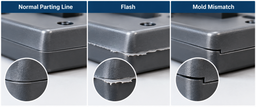
A parting line is the expected boundary created where mold sections meet.
Flash is excess plastic that extends beyond the intended geometry of the molded component.
A molded part can therefore have a visible injection molding parting line without having unacceptable flash. The presence of the line itself does not necessarily indicate a tooling or molding problem.
When flash appears around the parting area, several possible causes should be considered rather than immediately assuming the mold was manufactured incorrectly.
These can include:
- Insufficient clamping force
- Excessive cavity pressure
- Poor fitting or damage at the parting surface
- Local mold deflection
- Inappropriate processing conditions
- Wear after repeated production cycles
For example, flash that appears only in one local area may point toward a different problem than flash that develops around a large portion of the mold perimeter.
The appropriate corrective action depends on the actual cause. This is why the molded part, mold condition, and processing parameters should be evaluated together.
How Is the Parting Line Location Determined?
Choosing an injection molding parting line is not simply a matter of drawing a line around the CAD model. Its location should be evaluated together with mold opening direction, part geometry, draft, undercuts, cosmetic requirements, and functional surfaces.
The mold designer needs to consider how the component will be formed, how the mold will open, how the part will remain on the intended side of the tool, and how it will eventually be ejected.
Several factors are normally reviewed together.
Mold Opening Direction
The opening direction is one of the first considerations.
The geometry needs to release when the mold opens. Features that lock the part against the opening direction may create undercuts and require sliders, lifters, collapsible cores, or another mold mechanism.
Because of this, the injection molding parting line and mold opening direction are closely connected. Changing one can affect how the other needs to be designed.
Part Geometry
A simple rectangular cover may allow a relatively straightforward parting strategy.
A product with curved surfaces, side openings, stepped edges, clips, or irregular geometry may require a more complex parting surface.
The parting surface itself does not always need to be flat. Depending on the component, it may follow steps, curves, or changes in the product geometry.
Draft Angle
Draft determines whether vertical surfaces can release from the mold.
Changing the parting line may change which surfaces belong to the core side and cavity side and, consequently, the direction in which draft needs to be applied.
For this reason, draft and parting line should not be reviewed independently.
Undercuts
Side holes, hooks, clips, and recessed features can create undercuts in injection molded plastic parts that interfere with the normal mold-opening direction.
Sometimes changing the parting strategy can simplify an undercut. In other cases, a slider or lifter is still necessary.
The right decision depends on the complete geometry rather than one isolated feature.
Cosmetic Requirements
For an appearance-sensitive enclosure, the location of the injection molding parting line can be important.
Where possible, designers may position it along:
- Existing product edges
- Changes in geometry
- Less visible surfaces
- Non-cosmetic areas
However, hiding the line should not create unnecessary tooling complexity without considering the benefit.
Functional and Assembly Surfaces
A visually acceptable location is not always a functionally acceptable location.
Parting lines passing through locating surfaces, snap fits, sealing areas, or mating edges may require closer control because flash or mismatch can influence how the product functions or assembles.
Different Part Geometries Lead to Different Parting Strategies
There is no single injection molding parting line layout suitable for every plastic component. The appropriate strategy depends on part geometry, appearance requirements, mold opening direction, and tooling complexity.
Straight or Flat Parting
For relatively simple parts, the mold may separate around a flat or nearly flat plane.
This generally provides a simpler tooling arrangement and makes manufacturing and fitting of the mold more straightforward.
When the product geometry allows it, a simple parting surface can also make mold maintenance and later adjustments easier.
Stepped Parting
If the product edge changes height, the parting surface may need to follow those changes.
This can help keep the visible parting line near the natural edge of the component, although the mold becomes more complicated to machine and fit than a simple flat parting surface.
Additional attention may also be required around transitions and shut-off areas.
Curved or Contoured Parting
Products with curved exterior geometry may require the parting surface to follow the shape.
This can help manage appearance requirements but requires careful tooling work to maintain good contact along the mating surfaces.
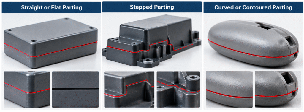
The important point is that parting line selection is a balance.
The visually cleanest solution is not always the most robust tooling solution, while the simplest mold construction may not always provide the appearance or functional result required by the product.
Why Parting Line Location Matters to the Finished Plastic Part
The location of an injection molding parting line can affect much more than the appearance of an individual molded component. Its impact becomes clearer when the part is evaluated as part of a complete product.
1. Cosmetic Appearance
Consider a handheld plastic enclosure.
A parting line positioned along the side edge may be relatively unobtrusive. If the same line crosses the center of a high-gloss front surface, it may become much more noticeable.
Texture can add another consideration.
A textured surface near the parting area requires careful transition and mold fitting because differences across the boundary may become visually noticeable.
For appearance-sensitive products, cosmetic areas should therefore be identified during DFM rather than after the first samples have been molded.
2. Flash and Edge Quality
Flash around the injection molding parting line can create more than an appearance issue.
Depending on where it occurs, it may produce:
- Sharp edges
- Interference between components
- Additional trimming work
- Inconsistent assembly
- An unacceptable tactile surface
This is especially important for edges that users touch or areas where two molded components fit together.
3. Dimensional Consistency
Critical features located across or very close to the parting line deserve additional attention.
For example, if a critical hole is formed by features from both mold halves, any mismatch between those features can influence the resulting geometry.
The same consideration applies to:
- Locating features
- Mating edges
- External dimensions
- Snap-fit interfaces
- Sealing areas
This does not mean these features can never be located near a parting line. It means their function and tolerance requirements should be considered when the mold is designed.
4. Fit and Final Assembly
This is an area that can easily be overlooked if molded parts are evaluated only individually.
Imagine an upper housing and lower housing designed to snap together.
Both parts may pass a basic visual inspection separately. But if flash or mismatch exists along their mating edges, problems may appear during assembly:
- The housings may not seat completely
- The perimeter gap may become inconsistent
- Snap hooks may require excessive force
- Clips may not fully engage
- Operators may need to trim parts manually
- Cosmetic alignment may vary between assembled units
A tooling decision made early in the project can therefore affect a much later production stage.
For products that will be assembled after molding, DFM should consider the finished assembly, not just each plastic component in isolation.
This becomes especially important in plastic enclosure assembly, where housing alignment, clips, mating edges, gaps, and fastening features need to work together consistently.
Common Parting Line Problems We Check During Mold Trials
T1 and subsequent mold trials are not only used to see whether the mold can produce a complete part. They also show whether the selected injection molding parting line performs as expected under actual molding conditions.
Flash Along the Parting Line
If flash appears along the injection molding parting line, the first question should be where it occurs and whether it is consistent.
A local area of flash and flash around much of the mold perimeter may point toward different conditions.
Tooling fit, processing parameters, cavity pressure, clamping conditions, and local geometry may all need to be reviewed.
Simply trimming the sample may make the part look better, but it does not identify why the flash occurred.
For additional reference, Protolabs’ injection molding design guidance discusses design considerations related to parting lines, shut-offs, and injection-molded part manufacturability.
Mismatch or Mold Shift
A visible step across the parting line may indicate that the surfaces formed from opposite sides of the mold are not aligning as intended.
The inspection may involve:
- Mold alignment
- Inserts
- Shut-off surfaces
- Parting surface fitting
- Related tooling components
If the area is functional or cosmetic, even a relatively small mismatch may need attention.
Sharp or Rough Edges
The part may have an edge that is dimensionally close to specification but still feels sharp or rough.
If that edge is handled by the end user or contacts another component during assembly, its practical impact should be evaluated rather than relying only on dimensional inspection.
Cosmetic Inconsistency
Sometimes the issue is not flash or mismatch but simply that the parting line is more visible than expected.
At this stage, engineers need to determine whether the condition can reasonably be improved through tooling adjustment or whether the original parting location itself is the limitation.
That distinction matters because moving a parting line after tooling has been manufactured can be much more difficult than changing it during DFM.
A Practical Example: Two-Piece Plastic Housing
Consider a product consisting of an upper and lower injection-molded housing.
The industrial design requires a clean exterior, while the two components use internal snap hooks and locating bosses for assembly.
At first glance, placing the injection molding parting line around the outer perimeter seems straightforward. In practice, its location still needs to be checked against cosmetic, tooling, dimensional, and assembly requirements.
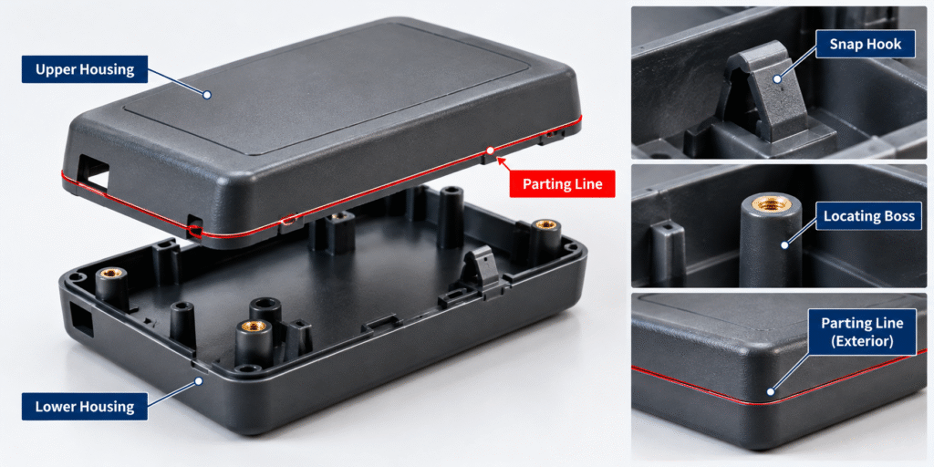
Several questions need to be answered.
Where Is the Cosmetic Boundary?
If the parting line moves onto the main visible surface, it may become unacceptable even if the part is dimensionally correct.
The product team therefore needs to identify which surfaces will be visible during normal use before the mold structure is finalized.
Where Are the Snap Hooks Located?
If a hook or its mating edge sits directly at a complicated shut-off, the tooling arrangement may become more difficult and flash could affect engagement.
The relationship between the hook, parting line, draft, and mold opening direction should therefore be reviewed together.
Which Dimensions Control the Assembly Gap?
If important mating features are formed from different mold sections, their relationship needs to be considered.
A small dimensional variation on an isolated molded part may appear acceptable but become more noticeable when the upper and lower housings are assembled.
Does Moving the Line Simplify or Complicate the Mold?
A more visually hidden line may require additional machining or more complicated tooling geometry.
This is why there is rarely a useful rule such as always hiding the parting line.
The correct decision depends on the priorities of the actual product.
Can Parting Lines Be Completely Eliminated?
For most conventional injection-molded parts, completely eliminating every indication of a mold separation interface is not a realistic design objective.
A more practical goal is to control the injection molding parting line so that it does not create an unacceptable cosmetic, functional, or assembly issue.
Depending on the design, this may involve:
- Locating it along a natural product edge
- Keeping it away from important cosmetic surfaces
- Improving parting-surface fitting
- Controlling molding conditions
- Minimizing mismatch
- Controlling flash
- Applying appropriate secondary finishing when justified
But every improvement has to be considered in context.
Moving a line to hide it visually may increase tooling complexity. Adding mechanisms can increase mold cost and maintenance requirements. A complicated shut-off may be less robust than a simpler alternative.
Good mold design therefore involves trade-offs rather than pursuing one characteristic in isolation.
Why We Review the Parting Line During DFM
Reviewing the injection molding parting line during DFM helps identify potential tooling, cosmetic, dimensional, and assembly conflicts while changes to the product are still relatively easy to make.
During DFM, the process is not simply:
Find a location → Draw the parting line → Start tooling
Instead, several related elements are evaluated together:
Mold opening direction → Draft → Undercuts → Parting strategy → Cosmetic requirements → Critical dimensions → Assembly interfaces
For example, suppose a plastic housing contains a snap hook near the proposed parting line.
The review may need to consider:
- Is the hook an undercut?
- What mold movement is required?
- Where will the shut-off be?
- Could flash affect the hook?
- Is sufficient draft available?
- Does the parting line cross the mating area?
- Can the feature be adjusted easily after T1?
- Could a small design change simplify the mold?
Sometimes moving a feature by a small amount during the design stage can avoid a much more complicated tooling solution.
That is one of the main purposes of DFM: to identify these relationships before the design becomes expensive to change.
What Should Be Checked During T1?
Once the first molded samples are available, the injection molding parting line should be evaluated as part of the overall T1 review.
Typical checks include:
- Is there visible flash?
- Is there mismatch across the line?
- Are cosmetic areas acceptable?
- Are edges smooth enough for handling?
- Are critical dimensions near the line within requirements?
- Do mating parts fit correctly?
- Do snap features engage consistently?
- Is trimming or rework required?
- Does the condition remain stable across multiple samples?
The final point is particularly important.
A single acceptable sample does not necessarily demonstrate a stable molding condition.
For example, if one T1 sample shows a clean mating edge but several later samples begin to show flash or inconsistent fit, the condition should be investigated before the tooling is considered ready for production.
The behavior should therefore be reviewed across multiple molded parts and, where relevant, under representative production settings.
What Should Be Confirmed Before Tooling Starts?
Before mold manufacturing begins, the proposed injection molding parting line should be reviewed together with the other key DFM requirements.
Product teams can reduce later uncertainty by confirming several points:
- Where is the proposed parting line?
- What is the mold opening direction?
- Which surfaces are cosmetic?
- Is the line visible during normal product use?
- Is it close to a mating or sealing surface?
- Does it pass through a critical dimension?
- Are snap fits or locating features nearby?
- Could flash interfere with assembly?
- Are any complicated shut-offs required?
- Would moving the line simplify or complicate the mold?
- Has the parting strategy been clearly shown in the DFM review?
These questions are much easier to discuss on a CAD model than after steel has already been cut.
They also give the product designer and mold manufacturer an opportunity to discuss trade-offs before tooling cost and lead time have already been committed.
Final Thoughts
An injection molding parting line may appear to be only a thin mark on a plastic component, but behind that line is an important mold-design decision.
Its position can influence:
- Mold construction
- Part appearance
- Flash control
- Dimensional consistency
- Assembly fit
- Tooling complexity
The best parting line is therefore not necessarily the one that is completely hidden, nor is it always the one that produces the simplest mold.
It is the one that provides the right balance for the product.
At CINDY Mould, injection molding parting line location is reviewed during DFM together with mold opening direction, draft, undercuts, cosmetic requirements, critical features, and downstream assembly needs.
Reviewing these relationships before tooling begins gives both the product designer and mold manufacturer more room to solve potential problems before they become expensive tooling changes.