Gate location is one of the most influential design decisions in injection molded plastic parts. While gate type and size affect filling characteristics, the position of the gate fundamentally determines how pressure, temperature, and material flow distribute across the cavity.
From a Design for Manufacturability (DFM) standpoint, gate location governs flow symmetry, packing transmission efficiency, shrinkage direction, weld line formation, and long-term dimensional stability. A gate position that appears acceptable during early mold trials may later introduce warpage, cosmetic defects, or cavity imbalance during sustained production.
Proper gate location must therefore be treated as a structural and thermal control strategy—not merely a tooling convenience.
1. Gate Location and Flow Front Progression
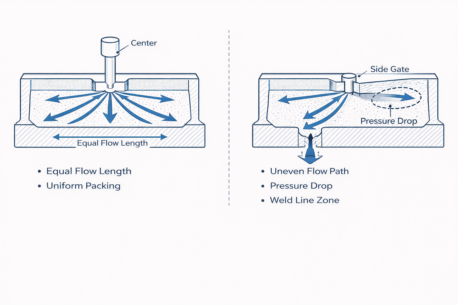
When molten polymer enters the cavity, the gate defines the origin of the flow front. From that point forward, melt viscosity, shear rate, and pressure begin to change along the flow path.
As the melt travels:
• Temperature decreases
• Viscosity increases
• Pressure drops progressively
• Flow resistance accumulates
If gate location creates excessive flow length or asymmetric paths, pressure loss becomes uneven. This leads to incomplete packing in remote regions and higher internal stress concentration near the gate.
Balanced gate positioning reduces differential flow resistance and improves structural uniformity across the part.
2. Pressure Transmission and Packing Efficiency
Packing pressure compensates for volumetric shrinkage during solidification. However, pressure transmission is not uniform across long flow paths.
As distance from the gate increases:
• Pressure decay intensifies
• Material density decreases
• Shrinkage becomes more pronounced
If thick sections are positioned far from the gate, they may not receive sufficient packing pressure before gate freeze-off occurs.
Gate location should therefore prioritize efficient pressure transmission to high-mass regions of the part.
3. Gate Freeze-Off and Dimensional Stability
Gate freeze-off refers to the moment when the material at the gate solidifies during polymer crystallization, preventing further packing pressure transmission.
If gate freeze occurs prematurely:
• Remote regions continue shrinking without compensation
• Internal stress becomes uneven
• Warpage risk increases
Gate location influences freeze-off timing because thicker flow paths near the gate retain heat longer, while distant thin walls may solidify earlier.
Proper gate placement ensures that pressure remains effective long enough to stabilize dimensional accuracy.

4. Gate Location Relative to Ribs and Reinforcement Features
Reinforcement structures such as ribs and bosses significantly alter melt flow behavior.
Proper rib design must be coordinated with gate positioning to ensure balanced flow and packing efficiency.
When flow splits around rib networks:
• Weld lines may form
• Packing becomes inconsistent
• Stress concentration increases
Gate location must support balanced filling across reinforcement zones to prevent weak weld interfaces or uneven density distribution.
Positioning the gate directly opposite complex rib clusters often improves structural integrity.
Similar considerations apply to boss structures, where flow splitting and packing balance influence long-term dimensional stability.
5. Shrinkage Direction and Warpage Mechanism
Gate location directly influences shrinkage orientation.
Because polymer chains align along primary flow direction:
• Shrinkage tends to occur along that axis
• Internal stress becomes directional
• Warpage may follow predictable bending patterns
Asymmetric gate positioning often results in twisting or panel distortion, particularly in large flat parts.
Balanced central gating reduces directional shrinkage bias.
6. Thermal Interaction and Cooling Balance
Regions near the gate typically experience:
• Higher shear heating
• Longer packing duration
• Greater localized density
This creates thermal gradients between gate-adjacent and remote regions.
If cooling channels are not designed to compensate for this imbalance, residual stress accumulates during repetitive production cycles.
Gate location and cooling strategy must be evaluated simultaneously during DFM review.
7. Multi-Cavity Flow Balance
In multi-cavity molds, even small differences in gate location or runner symmetry can amplify variation.
Common issues include:
• Unequal cavity weight
• Dimensional inconsistency
• Flow hesitation in outer cavities
• Differential freeze timing
Gate location must maintain equal flow length and pressure distribution across cavities to ensure production consistency.
Symmetry is critical in high-volume manufacturing.
8. Why Gate Issues Often Appear in Mass Production
During T0 or T1 trials:
• Production runs are short
• Process parameters are closely monitored
• Packing adjustments compensate for minor imbalance
In mass production:
• Material lot variation changes viscosity
• Cooling efficiency fluctuates
• Minor pressure imbalance accumulates
• Cycle time adjustments expose structural weaknesses
Gate location that seemed acceptable in sampling may gradually lead to instability during extended production.
9. Common Gate Location Mistakes in Practice
Recurring DFM errors include:
• Placing gates based solely on tooling convenience
• Gating directly onto cosmetic surfaces
• Ignoring long flow paths to thick sections
• Creating asymmetric filling patterns
• Failing to analyze reinforcement interaction
These design shortcuts often introduce long-term instability rather than immediate failure.
10. DFM Checklist for Gate Location Evaluation
Before final tooling approval, evaluate:
▸ Is filling symmetrical across the cavity?
▸ Are thick sections adequately packed?
▸ Is freeze-off timing controlled?
▸ Are weld lines positioned away from high-stress zones?
▸ Is shrinkage direction predictable?
▸ Is multi-cavity balance validated?
▸ Does cooling layout support gate position?
Proper draft angle design should also be reviewed to maintain stable mold release after optimized gate placement.
Systematic evaluation reduces structural and cosmetic risk.
Conclusion
Gate location guidelines for injection molded plastic parts extend beyond simple flow entry considerations. Gate location governs pressure transmission, thermal balance, shrinkage orientation, and long-term dimensional stability.
Proper gate positioning integrates flow physics, packing mechanics, and thermal control into a unified DFM strategy. When carefully evaluated, gate location enhances structural integrity, reduces warpage, and ensures stable high-volume production.
In injection molding, gate location is not merely a geometric choice—it is a primary determinant of manufacturing consistency.