Undercut design is a structural decision that significantly influences injection mold construction, tooling cost, and long-term production stability. While undercuts are often introduced to improve part functionality, retention strength, or assembly locking performance, they complicate mold release mechanisms and increase mechanical wear points within the tooling system.
In injection molded plastic parts, improper undercut design frequently leads to increased tooling complexity, higher maintenance frequency, longer cycle times, and reduced scalability. Therefore, undercut geometry must be carefully evaluated during early DFM analysis to balance product performance with manufacturing feasibility.
Definition of Undercut in Injection Molding
An undercut is a molded feature that prevents direct straight-line ejection from a standard two-plate mold. When a molded part contains geometry that mechanically locks into the mold cavity or core, additional release mechanisms become necessary.
Typical undercut features include:
- Internal snap hooks
- Reverse-facing ribs
- Side holes perpendicular to parting direction
- Internal retaining grooves
- Threaded geometries
- Zero or negative draft locking surfaces
Undercuts create interference with the natural ejection direction and require specialized mold structures to enable part release.
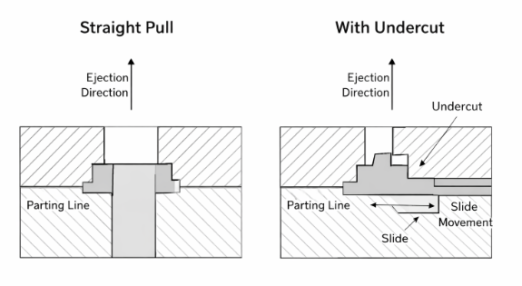
Figure 1. Undercut geometry interfering with straight pull ejection and requiring slide mechanism.
Industry guidance on molded feature design and tooling practices is often discussed by professional organizations such as the Society of Plastics Engineers (SPE).
Structural Characteristics of Undercut Geometry
Undercut design varies based on geometry depth, angle, and location relative to the parting line.
Key geometric variables include:
- Undercut depth
- Undercut angle
- Wall thickness surrounding the feature
- Distance from parting line
- Interaction with adjacent ribs or bosses
Shallow undercuts with limited mechanical locking effect may be released through controlled material deformation. However, deeper or rigid undercuts typically require side actions, lifters, or collapsible core systems.
The feasibility of release is directly influenced by material flexibility and shrinkage behavior.
Classification of Undercut Types
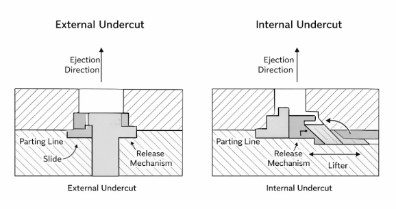
1. External Undercuts
External undercuts appear on outer surfaces of the part and typically require lateral release systems.
Common tooling solutions:
- Slide mechanisms
- Cam-driven side cores
- Hydraulic or mechanical side actions
These systems increase mold width and require additional alignment precision.
2. Internal Undercuts
Internal undercuts are often more complex. They are common in:
- Snap-fit housings
- Cylindrical components
- Threaded parts
- Assembly retention features
Tooling mechanisms for internal undercuts include:
- Lifters
- Collapsible cores
- Unscrewing systems
- Split cavities
Internal undercut design significantly increases mold cost due to mechanical complexity and precision requirements.
Tooling Implications of Undercut Design
Undercut design directly impacts mold structure and long-term durability.
Major tooling considerations include:
- Increased mold base dimensions
- Additional moving components
- More complex cooling channel routing
- Higher machining precision requirements
- Increased wear on slide rails and guide pins
Slides and lifters introduce dynamic mechanical interfaces that are subject to friction, thermal expansion, and alignment drift.
Over extended production cycles, these systems may cause:
- Flash formation near undercut regions
- Dimensional variation
- Increased maintenance downtime
- Lubrication dependency
The addition of even a single undercut feature may significantly increase tooling assembly time and part cost.
Undercut Depth and Material Flexibility
Not all undercuts require side actions. In flexible thermoplastics such as polypropylene (PP) or polyethylene (PE), shallow undercuts may be released by elastic deformation.
Release feasibility depends on:
- Material elongation properties
- Undercut depth-to-wall thickness ratio
- Feature width
- Cooling shrinkage characteristics
As a general engineering guideline:
- Undercuts less than 0.3–0.5 mm in flexible materials may be demolded without slides.
- Rigid materials such as ABS or PC typically require mechanical release systems for similar geometries.
Material selection must therefore be evaluated alongside undercut design decisions.
Interaction Between Undercut and Draft Angle
Undercut geometry frequently interacts with draft angle requirements. Negative draft or zero-draft locking features increase release resistance and slide wear.
Proper draft around undercut regions:
- Reduces friction during side core movement
- Improves mechanical clearance
- Extends slide system life
- Reduces galling
Designers should avoid combining deep undercuts with minimal draft in high-volume production applications.
Undercut regions with insufficient draft often become high-stress concentration zones during ejection.
Undercut and Wall Thickness Interaction
Undercut performance is also influenced by wall thickness distribution. Thick sections surrounding undercut features increase shrinkage force and create stronger mechanical locking against core components.
When thick walls and deep undercuts coexist:
- Ejection force increases significantly
- Deformation risk rises
- Slide wear accelerates
Uniform wall thickness and controlled feature transitions improve undercut release stability.
Undercut design should therefore be evaluated together with wall thickness control during DFM review.
Cost and Cycle Time Impact
Undercut design affects not only tooling cost but also production efficiency.
Additional slide movement may:
- Increase mold opening stroke
- Extend cycle time
- Increase machine tonnage requirements
Cycle time extension accumulates significantly in high-volume production environments.
In some applications, redesigning an undercut to allow straight pull molding may reduce overall production cost despite minor changes in part geometry.
Early cost modeling should include:
- Slide machining cost
- Maintenance interval projection
- Spare component requirements
- Downtime risk assessment
Cooling and Undercut Regions
Undercut structures may restrict optimal cooling channel placement. Slides and lifters often occupy space that would otherwise be used for cooling lines.
Inadequate cooling near undercut areas can result in:
- Localized shrinkage variation
- Warpage
- Dimensional drift
- Extended cooling time
Thermal imbalance in these regions increases mold wear and reduces dimensional consistency.
DFM Review Checklist for Undercut Design
During DFM analysis, undercut design should be evaluated against the following criteria:
- Is the undercut functionally necessary?
- Can geometry be modified to eliminate the undercut?
- What release mechanism is required?
- How does material selection affect release feasibility?
- Does the undercut interfere with cooling channels?
- Is slide maintenance feasible for projected production volume?
- What is the expected service life of moving components?
Early identification of non-essential undercuts often prevents costly mold redesign.
Common Engineering Mistakes in Undercut Design
Typical oversights include:
- Introducing undercuts for cosmetic features
- Underestimating slide wear rate
- Ignoring material shrinkage interaction
- Combining deep undercuts with high glass-fiber content materials
- Not analyzing tolerance stack-up in moving mechanisms
These mistakes frequently lead to:
- Flash at parting lines
- Slide galling
- Increased scrap rate
- Unexpected maintenance intervals
Undercut features often coexist with complex boss design in snap-fit housings, requiring coordinated structural evaluation.
Such issues may not appear during initial sampling but often become evident during long production runs.
Conclusion
Undercut design is a structural variable that significantly affects tooling complexity, production cost, and long-term mold durability. While undercuts may enhance product functionality, they introduce mechanical systems that require careful engineering evaluation.
By assessing undercut geometry, material interaction, draft angle compatibility, and tooling feasibility during DFM review, manufacturers can reduce risk and ensure scalable injection molding performance.