In injection molding projects, lead time often appears predictable during planning. Tooling schedules are defined, production capacity is calculated, and delivery milestones are approved based on expected cycle times and expected output.
On paper, the timeline looks stable.
However, once production ramp-up begins, delivery performance frequently starts to drift. What appeared stable during sampling or pilot runs becomes increasingly difficult to maintain under sustained output pressure.
This shift is rarely accidental. It reflects a structural transition in manufacturing conditions rather than isolated execution mistakes.
Ramp-up is not simply a volume increase phase.
It is the first sustained exposure of the molding system to real production stress.
Understanding why lead time becomes unstable during ramp-up requires separating structural causes from operational symptoms.
Sampling vs. Ramp-Up: A Fundamental Condition Shift
Sampling validates part capability.
Ramp-up validates system robustness.
Sampling confirms that a part can meet dimensional and cosmetic requirements.
Ramp-up tests whether that performance can be repeated consistently at scale.
Sampling focuses on feasibility.
Ramp-up exposes sustainability.
Many lead time issues originate in the gap between these two stages.
Structural Causes of Lead Time Instability During Ramp-Up
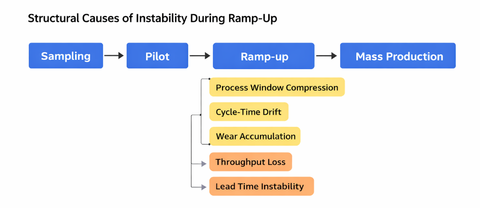
1. Continuous Tooling Exposure
During trials, molds operate for limited durations under controlled supervision. Ramp-up shifts the mold into continuous cycling, where thermal fluctuation and mechanical wear begin to accumulate.
Gate geometry, runner transitions, and venting efficiency gradually change under repetitive stress. Minor deviations that were insignificant during short runs begin to influence filling balance and packing behavior.
Over thousands of cycles, these small mechanical changes translate into measurable output variation.
2. Process Window Compression
Sampling often confirms that a part can be molded within specification. Ramp-up tests whether it can remain stable under tighter efficiency constraints.
Cycle time is optimized, hold pressure is adjusted for throughput, and cooling time is minimized. If tooling design provides limited process margin, even small fluctuations in viscosity, material batch variation, or ambient temperature narrow the operating window further.
The process becomes increasingly dependent on adjustment, increasing variability in both quality and output.
3. Waste Amplification Under Volume Pressure
At low production volume, scrap and minor rework may not visibly affect delivery schedules. During ramp-up, the same defect rate directly reduces available production capacity.
A 2–3% scrap rate that seemed manageable during validation can disrupt weekly shipment targets once volume scales. Recovery time shortens while pressure increases.
Small inefficiencies compound quickly.
4. Alignment Gaps Between Functions
Ramp-up tests coordination between engineering, production, quality, and supply chain management.
Material supply timing, insert replacement intervals, preventive maintenance planning, and inspection capacity must align. Assumptions made independently during early planning often conflict under sustained output conditions.
Lead time instability is frequently the visible symptom of cross-functional misalignment rather than a single technical failure.
5. Hidden Cycle-Time Drift
Ramp-up instability rarely appears as dramatic breakdown. More often, it manifests as incremental adjustments:
- Holding pressure extended by one or two seconds
- Cooling time increased to reduce deformation
- Additional inspection steps introduced
Each change appears minor in isolation. Collectively, they reduce available throughput and extend delivery timelines.
Efficiency erosion is typically gradual rather than sudden.
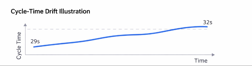
Case Illustration: Cycle-Time Drift in Ramp-Up
In one interior automotive component program, the validated cycle time during pilot production was 29 seconds. Within three weeks of ramp-up, the cycle increased to 32 seconds.
The initial adjustment was introduced to reduce slight cosmetic variation near a gate region. The change appeared insignificant.
However, across high-volume output, the additional three seconds reduced weekly capacity by nearly 9%. Delivery schedules required restructuring, and overtime was introduced to compensate.
The issue was not machine malfunction. It was marginal process margin exposed under sustained production conditions.
Ramp-up did not create the instability. It revealed it.
Quantifying the Impact of Instability
Small time differences have measurable effects at scale.
An additional three seconds on a 30-second baseline represents roughly a 10% reduction in throughput. Over 100,000 cycles, this difference can translate into hundreds of lost production hours.
Similarly, minor increases in scrap or rework directly reduce effective output capacity and increase schedule volatility.
Lead time instability is often the cumulative result of marginal design, validation, or coordination decisions.
Practical Control Strategies for Stable Ramp-Up
Addressing ramp-up instability requires structural preparation rather than reactive correction.
1. Extended-Duration Validation
Tooling should be evaluated under sustained production cycles, not only short validation runs. Monitoring cycle stability, part weight variation, and temperature behavior over extended periods reveals early instability trends.
Ramp-up readiness should be demonstrated under realistic production exposure.
2. Process Window Evaluation
Instead of validating a single optimal parameter set, teams should test process stability across realistic variation ranges in material viscosity and environmental conditions.
A robust process window reduces reliance on constant parameter tuning during scaling.
3. Wear-Impact Assessment
High-shear and high-pressure regions—particularly gates and runner transitions—should be evaluated for long-term geometric stability.
Predicting wear behavior early reduces later cycle-time drift and unexpected downtime.
4. Cross-Functional Ramp-Up Planning
Engineering, production, quality, and supply chain teams should align ramp-up assumptions before increasing output.
Maintenance intervals, spare insert readiness, inspection capacity, and material supply consistency should be reviewed collectively.
Alignment reduces reaction time when instability appears.
Ramp-Up Stability Checklist
Before increasing production volume, teams should confirm:
- Has the mold operated continuously for extended validation cycles?
- Is process stability verified under realistic material variation?
- Are high-wear regions monitored for early geometry change?
- Is preventive maintenance scheduled based on cycle count rather than calendar estimates?
- Is there sufficient process margin to absorb minor environmental fluctuation?
Structured preparation significantly reduces delivery volatility during ramp-up.
Conclusion
Lead time instability during production ramp-up is rarely accidental. It is typically rooted in structural factors that were not fully exposed during early validation stages.
Ramp-up is not a confirmation phase.
It is a stress phase.
Stable delivery performance is not achieved through scheduling alone. It is engineered through sufficient process margin, realistic long-run validation, wear awareness, and cross-functional alignment before production pressure increases.
In injection molding, consistency at scale is the true measure of system robustness. Lead time stability reflects the strength of decisions made long before volume accelerates.