Mold Cooling Design Guide: Cooling Channel Layout and Best Practices

Mold cooling design determines how efficiently and uniformly heat is removed from an injection molded part. Although filling and packing receive much of the attention during mold trials, cooling usually occupies the largest portion of the molding cycle and strongly affects dimensional stability, warpage, surface quality, cycle time, and long-term production consistency.

A mold may produce acceptable samples during early trials even when its cooling system is marginal. Longer trial cycles, frequent parameter adjustments, and limited heat accumulation can temporarily hide thermal imbalance.

Once production runs continuously and cycle times are reduced, the same mold may begin to show unstable dimensions, inconsistent warpage, rising scrap rates, or gradual cycle-time drift.

Effective mold cooling design is therefore not simply about lowering mold temperature. It is about maintaining controlled and repeatable thermal balance across the cavity, core, mold inserts, and every cavity in the tooling system.


What Is Mold Cooling Design?

mold cooling design impact on injection molding production stability

Mold cooling design is the engineering process used to determine how heat will be removed from the molded part and tooling during each production cycle.

It includes decisions involving:

  • Cooling-channel location
  • Channel diameter
  • Channel spacing
  • Distance from the cavity surface
  • Coolant flow direction
  • Circuit length
  • Number of cooling circuits
  • Core and cavity cooling balance
  • Cooling around ribs, bosses, and thick sections
  • Baffles, bubblers, thermal pins, and inserts
  • Conformal cooling where required
  • Coolant temperature, pressure, and flow rate
  • Maintenance and cleaning accessibility

These factors work together. A channel that is correctly positioned but receives insufficient flow may still provide poor cooling. Similarly, adequate total flow does not guarantee stability if different areas of the cavity cool at different rates.


Why Mold Cooling Design Matters

During injection molding, molten plastic transfers heat to the steel surfaces of the mold. That heat must then move through the mold material and into the circulating coolant before the part can be ejected safely.

Poor thermal control may cause:

  • Long cycle times
  • Cycle-time variation
  • Uneven shrinkage
  • Part warpage
  • Sink marks
  • Dimensional drift
  • Surface defects
  • Difficult ejection
  • Hot spots
  • Narrow process windows
  • Uneven cavity performance
  • Premature mold wear
  • Higher scrap rates

Cooling performance affects more than production speed. It determines whether the process can remain stable over hundreds of thousands of repeated cycles.


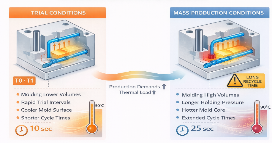
Why Successful Mold Trials Can Hide Cooling Problems

Early mold trials are typically conducted under controlled and relatively forgiving conditions.

Trial conditions may include:

  • Longer cooling times
  • Slower production cycles
  • Frequent parameter adjustments
  • Manual part inspection
  • Limited continuous operation
  • Lower heat accumulation in the mold
  • Experienced technicians monitoring every shot

Under these conditions, a marginal cooling system may still produce acceptable samples.

Mass production creates a different thermal environment:

  • Cycles run continuously
  • Cooling time is reduced to meet output targets
  • Mold temperature gradually stabilizes at a higher level
  • Automatic ejection requires consistent part stiffness
  • Small thermal differences repeat every cycle
  • Cavities and inserts may not heat evenly
  • Coolant conditions may vary over time

A cooling system should therefore be validated under realistic continuous-production conditions rather than judged only by early samples.


1. Heat Transfer in Injection Mold Cooling

Understanding heat transfer helps explain why cooling-channel layout matters.

Conduction Through the Mold

Heat moves from the molten plastic into the mold surface and then through the steel by conduction.

The rate of conduction depends on:

  • Mold-steel thermal conductivity
  • Distance between the cavity surface and cooling channel
  • Insert construction
  • Contact quality between mold components
  • Local part thickness
  • Temperature difference between the mold and coolant

Poor contact between an insert and the surrounding mold can act as a thermal barrier, even when a cooling channel is located nearby.

Convection Into the Coolant

Once heat reaches the cooling channel, it must transfer into the moving coolant.

Cooling performance depends on:

  • Coolant flow rate
  • Flow condition
  • Channel diameter
  • Coolant temperature
  • Circuit length
  • Surface condition inside the channel
  • Scale, rust, or contamination
  • Pump and manifold performance

A cooling channel containing stagnant or slow-moving water may remove heat less effectively than expected.

Thermal Gradient Formation

Thermal gradients develop when different areas of the mold cool at different rates.

These gradients may be caused by:

  • Uneven part thickness
  • Long distances between channels
  • Different core and cavity structures
  • Deep ribs or bosses
  • Hot-runner components
  • Inserts with different thermal conductivity
  • Unequal coolant flow
  • Complex geometry

Thermal gradients are a major source of uneven shrinkage and warpage.


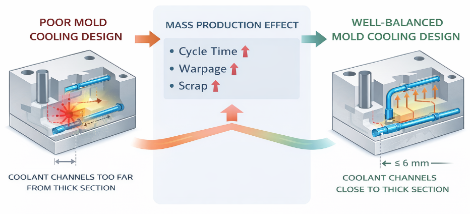
2. Cooling Channel Distance From the Cavity Surface

mold cooling design showing cooling channel distance from the cavity surface

Cooling channels must be close enough to remove heat effectively but far enough from the cavity surface to protect mold strength and avoid localized overcooling.

If a channel is too far from the cavity:

  • Heat removal becomes slow
  • Local hot spots may develop
  • Cooling time increases
  • Part temperature may remain uneven
  • Cycle time may drift

If a channel is too close:

  • The cavity surface may cool unevenly
  • Localized thermal marks may appear
  • Mold strength may be reduced
  • Cracking or water leakage risk may increase
  • Surface-temperature variation may become more severe

The correct distance depends on channel diameter, mold material, cavity geometry, part thickness, molding material, and structural requirements.

One fixed distance should not be applied to every mold.


3. Cooling Channel Spacing and Thermal Balance

Channel spacing determines how evenly heat is removed across the mold surface.

Channels placed too far apart may create alternating hot and cold zones. Channels placed very close together may increase manufacturing complexity without providing proportional improvement.

An effective layout should provide:

  • Consistent coverage around the cavity
  • Similar heat-removal capacity across critical areas
  • Balanced core and cavity temperatures
  • Predictable coolant flow
  • Minimal dead zones
  • Accessible connections for maintenance

Spacing should be evaluated according to thermal behavior rather than geometric symmetry alone.

A layout may look symmetrical in a drawing but still cool unevenly because part thickness and heat concentration are not symmetrical.


4. Cooling Thick Sections, Ribs, and Bosses

Thick sections retain heat longer than thin walls. Ribs, bosses, mounting structures, and deep cores can also create localized heat concentrations.

If these areas are not cooled effectively, they may cause:

  • Sink marks
  • Internal voids
  • Long cooling times
  • Uneven shrinkage
  • Difficult ejection
  • Local deformation
  • Dimensional instability

Cooling should follow the thermal load of the part. Areas containing more plastic may require additional cooling circuits, bubblers, baffles, thermal pins, or specially designed inserts.

However, aggressive cooling applied only to one feature can create a new thermal imbalance. Local cooling solutions must be evaluated as part of the complete mold system.


5. Core and Cavity Cooling Balance

The core and cavity sides of a molded part often have different structures and cooling limitations.

Deep cores generally retain more heat because:

  • Cooling channels are difficult to position near the surface
  • The core may have limited internal space
  • Heat must travel through a longer conduction path
  • Structural features may restrict channel routing

If the core remains hotter than the cavity, the two surfaces of the part may shrink differently. This can contribute to warpage, sticking, and dimensional variation.

Core and cavity temperatures do not always need to be identical, but their relationship should be intentional, stable, and validated.


6. Cooling Circuit Length and Flow Balance

Long cooling circuits can create temperature differences between the coolant inlet and outlet. As the coolant moves through the channel, it absorbs heat and becomes warmer.

Possible consequences include:

  • Strong cooling near the inlet
  • Weaker cooling near the outlet
  • Uneven cavity temperature
  • Different performance between mold zones
  • Increased sensitivity to flow variation

Large molds may require multiple independent cooling circuits instead of one long circuit.

Each circuit should be designed so that:

  • Flow resistance is manageable
  • Flow rate can be measured
  • Inlet and outlet temperatures can be monitored
  • Circuits can be cleaned independently
  • Critical mold areas receive sufficient cooling

Flow balance should be confirmed during mold validation and monitored during production.


7. Cooling Design for Multi-Cavity Molds

Multi-cavity molds require consistent thermal behavior across every cavity.

Even when the runner and gate system are balanced, uneven cooling may cause cavity-to-cavity variation in:

  • Part weight
  • Shrinkage
  • Dimensions
  • Warpage
  • Surface quality
  • Ejection behavior
  • Cycle readiness

Cooling circuits should not unintentionally favor cavities closest to the coolant inlet.

Multi-cavity cooling design should consider:

  • Similar circuit lengths
  • Balanced flow resistance
  • Comparable channel locations
  • Consistent core and cavity cooling
  • Individual cavity temperature measurement
  • Accessible flow-control points

Cavity balance must be evaluated thermally as well as rheologically.


8. Conventional Cooling Channels

Conventional cooling channels are normally produced by drilling straight passages through the mold plates, cores, or inserts.

Advantages include:

  • Lower manufacturing cost
  • Simple machining
  • Easier maintenance
  • Familiar production methods
  • Straightforward cleaning

Limitations include:

  • Restricted access to complex geometry
  • Difficulty following curved cavity surfaces
  • Poor coverage around deep features
  • Potential dead zones
  • Uneven distance from the molded surface

Conventional cooling works well when the part and mold geometry allow channels to be positioned consistently around the cavity.


9. Baffles and Bubblers

Baffles and bubblers redirect coolant into areas that cannot be reached effectively using straight drilled channels.

Baffles

A baffle divides a drilled channel and forces coolant to travel down one side and return along the other.

Baffles can improve cooling in deep mold sections but require correct installation and sealing. Poor positioning may create uneven flow or inactive zones.

Bubblers

A bubbler uses a tube to deliver coolant to the end of a deep core. The coolant then returns around the outside of the tube.

Bubblers are useful for narrow or deep cores but can become restricted by contamination or scale. Their internal condition should be considered during maintenance planning.


10. Thermal Pins and High-Conductivity Inserts

Thermal pins and high-conductivity inserts can help remove heat from localized areas where conventional water channels cannot be installed.

They may be applied around:

  • Deep cores
  • Small-diameter cores
  • Thick bosses
  • Narrow mold features
  • Local hot spots

These solutions can improve heat transfer, but they do not replace the need for an effective overall cooling system.

Insert fit, contact quality, material compatibility, wear resistance, and maintenance requirements should all be evaluated.


11. Conformal Cooling

Conformal cooling channels follow the shape of the cavity more closely than conventional drilled channels.

Potential benefits include:

  • More uniform surface temperature
  • Improved cooling of complex geometry
  • Reduced hot spots
  • Shorter cooling time
  • Lower warpage
  • More consistent dimensions

However, conformal cooling also introduces trade-offs:

  • Higher tooling cost
  • More complex manufacturing
  • Cleaning difficulty
  • Risk of internal blockage
  • Inspection challenges
  • Repair limitations
  • Material and durability considerations

Conformal cooling should be used where thermal analysis shows a meaningful production benefit rather than applied automatically to every mold.


12. Mold Material and Insert Interaction

Different mold materials conduct heat at different rates.

Tool steel may provide high wear resistance but conduct heat differently from copper alloys or specialized insert materials.

When multiple materials are used in one mold, engineers should consider:

  • Heat-transfer differences
  • Thermal expansion
  • Mechanical strength
  • Wear resistance
  • Corrosion behavior
  • Contact between components
  • Maintenance and replacement requirements

A high-conductivity insert can reduce a local hot spot, but poor contact with the surrounding mold may limit its effectiveness.


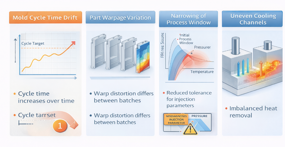
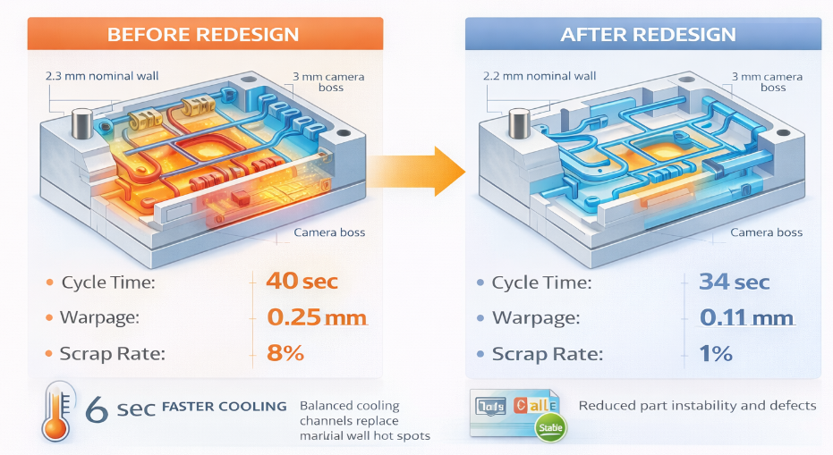
13. How Poor Cooling Design Affects Cycle Time

mold cooling design flaws causing cycle time drift and part warpage

Cooling time often represents the largest portion of the molding cycle.

When cooling is inefficient:

  • Parts remain too soft for ejection
  • Ejector marks may increase
  • Parts may deform after removal
  • Operators increase cooling time
  • Production output decreases

A marginal cooling system may also cause cycle-time drift. The mold may run well initially but require progressively longer cooling as heat accumulates.

Stable mold cooling design should support a repeatable cycle without depending on continuous manual adjustment.


14. How Poor Cooling Causes Warpage and Dimensional Drift

A molded part begins shrinking as it cools. If different areas cool at different rates, they also shrink at different times and by different amounts.

This may cause:

  • Bowing
  • Twisting
  • Local deformation
  • Hole-position variation
  • Assembly misalignment
  • Inconsistent flatness
  • Batch-to-batch dimensional changes

Warpage is rarely caused by cooling alone. Part geometry, wall thickness, material orientation, packing pressure, and gate location also contribute.

However, uneven cooling can amplify all these effects and make the process more sensitive to normal production variation.


15. Cooling Design and the Process Window

A wide process window allows production to remain stable despite small variations in material, ambient conditions, machine performance, and operating parameters.

Poor cooling narrows this window.

When thermal balance is marginal, small changes in coolant temperature, cycle time, or injection conditions may create visible differences in:

  • Dimensions
  • Warpage
  • Gloss
  • Shrinkage
  • Surface quality
  • Ejection behavior

A robust cooling system makes the process less dependent on constant parameter correction.


16. Cooling Design and Mold Wear

Uneven thermal cycling can create repeated expansion and contraction in the mold structure.

Over time, this repeated thermal stress can accelerate mold wear and structural fatigue.

The resulting long-term effects may include:

  • Insert movement
  • Localized fatigue
  • Seal deterioration
  • Water leakage
  • Parting-line instability
  • Uneven wear
  • Cracking around thermally stressed features

Cooling design should therefore consider long-term mold durability, not only immediate part temperature.


17. Cooling Simulation and Design Validation

Autodesk Moldflow provides cooling and warpage simulation tools that help engineers evaluate cooling-channel efficiency, temperature distribution, and cycle-time risks before tooling validation.

Cooling simulation can help identify:

  • Hot spots
  • Uneven cavity-surface temperatures
  • Insufficient channel coverage
  • Core and cavity imbalance
  • Temperature differences between cavities
  • Potential cycle-time limitations
  • Areas requiring alternative cooling strategies

Simulation results should be used as engineering guidance and then validated with physical measurements.

Useful validation methods include:

  • Coolant flow measurement
  • Inlet and outlet temperature monitoring
  • Cavity-surface temperature measurement
  • Thermal imaging
  • Part-temperature measurement
  • Part-weight studies
  • Dimensional studies
  • Warpage measurements
  • Continuous-production trials

Validation should use realistic molding parameters and sustained operating conditions.


18. Cooling System Maintenance

Even a well-designed cooling system can lose performance over time.

Common maintenance problems include:

  • Scale buildup
  • Rust
  • Sediment
  • Blocked bubblers
  • Restricted fittings
  • Damaged seals
  • Leaks
  • Incorrect hose connections
  • Reduced pump performance

Maintenance plans should include:

  • Periodic flow checks
  • Circuit cleaning
  • Leak inspection
  • Coolant-quality control
  • Hose and fitting inspection
  • Documentation of inlet and outlet connections
  • Comparison of flow data over time

A gradual decline in coolant flow may cause production instability before a complete blockage occurs.


Mold Cooling Design DFM Checklist

Before tooling release, review the following areas.

Part Geometry

  • Are thick sections identified?
  • Are ribs, bosses, and deep features thermally evaluated?
  • Is wall thickness reasonably uniform?
  • Are critical dimensions located near potential hot spots?
  • Is warpage risk understood?

Channel Layout

  • Are channels positioned consistently around the cavity?
  • Is the distance from the cavity surface appropriate?
  • Is channel spacing thermally balanced?
  • Are dead zones minimized?
  • Can the core and cavity be controlled effectively?

Cooling Circuits

  • Are circuit lengths manageable?
  • Is flow resistance balanced?
  • Can each circuit be measured independently?
  • Are inlet and outlet locations clearly identified?
  • Can circuits be cleaned and maintained?

Special Cooling Features

  • Are baffles or bubblers required?
  • Would thermal pins or high-conductivity inserts provide value?
  • Is conformal cooling justified by the expected production benefit?
  • Can specialized features be inspected and repaired?

Production Validation

  • Has cooling simulation been completed where necessary?
  • Will continuous production trials be performed?
  • Will cavity temperatures and coolant flow be measured?
  • Will warpage and dimensions be evaluated after thermal stabilization?
  • Is the target cycle time supported by actual cooling performance?

Frequently Asked Questions

Why is mold cooling design important?

Mold cooling design controls heat removal, cycle time, shrinkage, warpage, dimensional stability, ejection behavior, and long-term production consistency.

Why do cooling problems sometimes appear only in mass production?

Short mold trials may use longer cycles and do not always create the thermal accumulation found during continuous production. Mass production exposes marginal channel layouts and flow imbalance.

Should cooling channels be as close as possible to the cavity?

No. Channels must be close enough for effective heat transfer but far enough to maintain structural strength and avoid localized overcooling. The correct distance depends on the mold and part design.

What causes uneven cooling in an injection mold?

Common causes include inconsistent channel spacing, long cooling circuits, different core and cavity structures, thick part sections, blocked channels, low coolant flow, and unequal cavity coverage.

Can mold cooling design reduce warpage?

Improved thermal balance can reduce uneven shrinkage and residual stress, which are major contributors to warpage. Gate location, packing, wall thickness, and material behavior must also be considered.

Is conformal cooling always better?

No. Conformal cooling can improve complex thermal conditions, but it also increases tooling cost and maintenance complexity. It should be used when analysis demonstrates a clear production benefit.

How can cooling performance be validated?

Cooling performance can be evaluated using simulation, coolant-flow measurement, inlet and outlet temperatures, cavity-surface measurements, thermal imaging, dimensional studies, and sustained production trials.


Conclusion

Mold cooling design is a fundamental part of injection mold engineering. It affects much more than the temperature of the mold. It determines whether the process can maintain stable dimensions, predictable warpage, efficient cycle times, reliable ejection, and consistent quality during continuous production.

An effective cooling system requires balanced channel placement, suitable circuit length, controlled coolant flow, proper core and cavity coverage, and focused cooling around thermally demanding features.

Advanced solutions such as baffles, bubblers, thermal pins, high-conductivity inserts, and conformal cooling should be selected according to actual thermal requirements and lifecycle considerations.

Most importantly, cooling performance should be validated under realistic mass-production conditions. A mold that produces acceptable trial samples is not necessarily thermally stable enough for long-term production.

Get a Free Quote