Injection mold design defects are a major root cause of unstable production and quality issues in mass manufacturing.
In injection molding, mold design is the core foundation of production stability and final product quality—there’s no overstating its importance. In our daily mold design and mass production practice, we’ve found that 60%-70% of production defects (such as warpage, voids, and short shots) are not caused by process fluctuations or operator errors, but by overlooked flaws in the early mold design stage.
Common mold design flaws—like uneven wall thickness (exceeding industry allowances), improper venting structure, unreasonable gating system layout, and inadequate cooling circuit design—will directly lead to:
- Reduced production efficiency
- Rising scrap rates (even up to 10% in severe cases)
- Increased mold maintenance costs
- Premature mold failure (cutting mold life by 30%+)
Therefore, identifying and avoiding these design defects at the initial design stage, combining DFM (Design for Manufacturability) analysis with on-site production experience, is the key to ensuring stable mass production, reducing scrap costs, and extending mold service life. This article will detail common mold design defects, their root causes, and practical solutions based on our team’s years of mold design and production practice.
This aligns with the principles discussed in our DFM-focused articles, where early design decisions play a critical role in preventing downstream manufacturing risk.
Without addressing injection mold design defects during the design stage, process optimization alone cannot prevent recurring production failures.
Common Injection Mold Design Defects & Practical Solutions
Below are the most frequent mold design defects in actual production, along with their specific hazards, root causes, and actionable solutions—all verified through our on-site project experience.
Most injection mold design defects originate from early structural decisions that appear acceptable in trials but fail under mass production conditions.
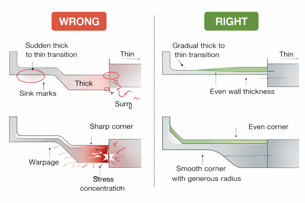
1. Uneven Wall Thickness
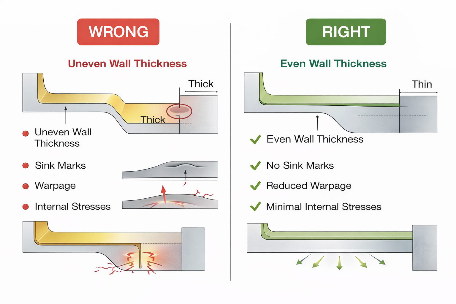
Uneven wall thickness is the most common and costly defect in injection mold design, especially for plastic parts with complex shapes (such as household appliance shells, automotive interior parts). It is mainly caused by unreasonable product structure design or improper mold flow path optimization, and its hazards are far more specific than general descriptions:
- Warpage & Dimensional Deviation
Different wall thicknesses lead to uneven cooling rates—thick sections cool slowly (shrinkage rate 1.2-2.5% for most plastics) and thin sections cool quickly (shrinkage rate 0.8-1.5%), resulting in internal stress buildup and part warpage.
For example, we once had a PP (polypropylene) automotive clip with a wall thickness varying from 1.8mm to 4.2mm; the warpage after molding reached 0.35mm, exceeding the customer’s tolerance of ±0.15mm, leading to an 8% scrap rate. - Surface Defects
Uneven material flow caused by thickness variation leads to flow marks, sink marks, and air pockets. Thick sections are prone to sink marks (depth ≥0.05mm is unacceptable for cosmetic parts), while thin sections may have underfilling or flow lines. - Extended Cycle Time
To reduce internal stress from uneven cooling, we have to extend the cooling time—for a part with 3mm-5mm thickness variation, cooling time may increase by 10-15 seconds, reducing production efficiency by 20%+.
Practical Solutions (Verified in Projects):
- Follow Uniform Thickness Guidelines
For most plastic materials (ABS, PP, PC, PA), the wall thickness should be controlled between 1.5-3.0mm, and the thickness difference between adjacent sections should not exceed 30%.
For example, if the main wall thickness is 2.0mm, the adjacent thickest section should not exceed 2.6mm. If thickening is required (e.g., for structural strength), use ribs (thickness 0.6-0.8 times the main wall) instead of increasing the overall thickness. - Optimize Flow Paths with Mold Flow Analysis (MFA)
Use MFA tools (such as Autodesk Moldflow, Simcenter 3D) to simulate material flow and cooling. Adjust the gating position and runner size to ensure uniform material filling.
For example, for a complex household appliance shell (ABS material), we used MFA to adjust the gating from the edge to the center, optimizing the runner diameter from 8mm to 6mm, which reduced wall thickness variation from 0.8mm to 0.2mm, and eliminated warpage defects. - Add Transition Fillets
For thickness transitions, add fillets with R≥0.5mm to avoid sharp corners—this reduces material flow resistance and uneven stress distribution.
2. Venting Issues
Among common injection mold design defects, inadequate venting is one of the most underestimated risks in high-volume production.
Poor venting is another common design defect, often overlooked in early design. It occurs when the mold lacks sufficient venting channels, or the venting position is unreasonable, leading to trapped air in the mold cavity during injection. In mass production, this defect can cause continuous scrap and production interruptions.
Specific Hazards:
- Bubbles & Voids
Trapped air cannot escape, forming bubbles (surface visible) or voids (internal, invisible but affecting structural strength).
For example, in a PC transparent part (used for lenses), even tiny bubbles (diameter ≥0.1mm) will lead to scrap, as they affect light transmittance. - Short Shots (Incomplete Filling)
Trapped air creates back pressure, preventing the mold cavity from being fully filled—especially for thin-walled parts (thickness ≤1.5mm) or complex cavities.
We once had a PA66 gear part (wall thickness 1.2mm) with no venting channels; the short shot rate reached 12% in mass production. - Burn Marks
Trapped air is compressed and heated (temperature can reach 200-300°C), causing plastic degradation and burn marks on the part surface—common in high-temperature materials (such as PC, PBT).
Practical Solutions (Industry Standard & On-Site Experience):
- Standard Vent Hole Design
- Vent hole depth: Determined by plastic material—0.02-0.03mm for high-viscosity materials (PC, PMMA), 0.04-0.05mm for low-viscosity materials (PP, PE); depth exceeding 0.06mm will cause flash.
- Vent hole width: 3-5mm (for small parts) to 8-10mm (for large parts), ensuring sufficient air escape area.
- Vent hole length: 5-8mm, extending to the mold outside to avoid air backflow.
- Optimize Venting Position
Venting channels should be placed at the end of material flow, opposite the gate, and in narrow/small cavities (where air is most likely to be trapped).
For example, for a gear part, we added 4 vent holes (0.04mm deep, 4mm wide) at the tooth tips (material flow ends), which reduced the short shot rate from 12% to 0.3%. - Special Venting for Complex Parts
For deep-cavity or thin-walled parts, use venting inserts (with 0.02-0.03mm gaps) or exhaust runners (diameter 2-3mm) to enhance venting.
For example, a deep-cavity plastic bucket mold (PP material) used venting inserts in the bottom cavity, eliminating bubble defects completely.
3. Mold Wear & Premature Failure Caused by Injection Mold Design Defects
Injection mold design defects related to material selection and structural stress are often the root cause of premature mold wear.
Mold wear is not just a production maintenance issue—it is largely determined by mold design and material selection. In mass production (100k+ mold cycles), unreasonable design will accelerate mold wear, leading to unstable product quality and increased downtime.
Common Wear Issues & Root Causes:
- Cavity Surface Damage
Scratches, wear, or cracking on the cavity surface—caused by improper material selection (e.g., using ordinary steel instead of wear-resistant steel), lack of heat treatment, or sharp corners in the cavity (stress concentration leads to cracking).
For example, a mold using P20 steel (without quenching) for an ABS part had cavity wear after 50k cycles, resulting in rough part surfaces (scrap rate 5%). - Dimensional Deviation
Wear of core, cavity, or guide pins leads to increased part dimensional tolerance, failing to meet customer requirements.
For example, a guide pin with insufficient hardness (HRC <45) wore out after 80k cycles, causing part misalignment (dimensional deviation ≥0.2mm). - Mold Sticking
Unreasonable ejection system design (e.g., insufficient ejector pins, uneven ejection force) leads to part sticking to the mold, requiring manual demolding—this scratches the cavity surface and accelerates wear.
Practical Solutions:
- Wear-Resistant Material Selection & Heat Treatment
- Cavity/core material: For mass production (≥100k cycles), use wear-resistant steel such as 718H, S136, or H13. 718H (quenched to HRC 52-56) is suitable for general plastic parts (ABS, PP); S136 (HRC 54-58, corrosion-resistant) is suitable for transparent parts (PC, PMMA) or corrosive materials (PVC).
- Guide pins/sleeves: Use SUJ2 steel (HRC 58-62) with surface nitriding treatment to enhance wear resistance.
- Maintenance-Friendly Design
- Incorporate replaceable components (e.g., insert cores, wear plates) for easy replacement after wear—avoiding the need to rework the entire mold.
For example, a mold for an automotive bumper bracket uses replaceable insert cores; when worn, we only need to replace the inserts (cost $200-$500) instead of the entire core (cost $2k-$3k).
- Incorporate replaceable components (e.g., insert cores, wear plates) for easy replacement after wear—avoiding the need to rework the entire mold.
- Optimize Ejection System
Ensure sufficient ejector pins (density ≥1 pin per 50cm²), uniform ejection force, and add draft angle (draft angle ≥1° for ABS, ≥2° for PP) to avoid mold sticking.
Conclusion
Injection mold design defects are often misunderstood as production issues, but in reality they originate from early design-stage decisions..
Ultimately, injection mold design defects should be treated as design-stage risks, not production issues discovered too late.
By implementing the systematic design optimization measures and solutions detailed in this article, we can effectively avoid common mold design defects, ensure stable production, reduce scrap costs, and extend mold life—ultimately helping enterprises achieve higher production efficiency and profitability.
For readers who want a general overview of injection molding fundamentals, a basic explanation of the injection molding process is available on Wikipedia.