
Draft angle injection molding plays a critical role in production, yet many problems don’t appear where teams expect them to.
Drawings are approved.
Mold trials pass.
Initial samples eject smoothly with clean surfaces and acceptable dimensions.
From the outside, everything looks ready for mass production.
Then production ramps up—and issues quietly begin to surface.
Parts start sticking in the mold. Cosmetic surfaces develop drag marks that weren’t visible before. Cycle times slowly increase to keep parts running. Mold wear accelerates earlier than planned. Maintenance frequency rises, scrap increases, and production teams begin making small adjustments just to stay on schedule.
In many cases, the root cause is not material quality, machine settings, or operator skill.
It is a design detail that often seems minor on paper but becomes critical in real manufacturing: draft angle.
This small taper on vertical walls is far more than a geometric afterthought. In high-volume injection molding, draft angle plays a central role in ejection behavior, surface quality, mold durability, and long-term production stability.
Draft Angle Injection Molding Is Not Just a Drawing Requirement
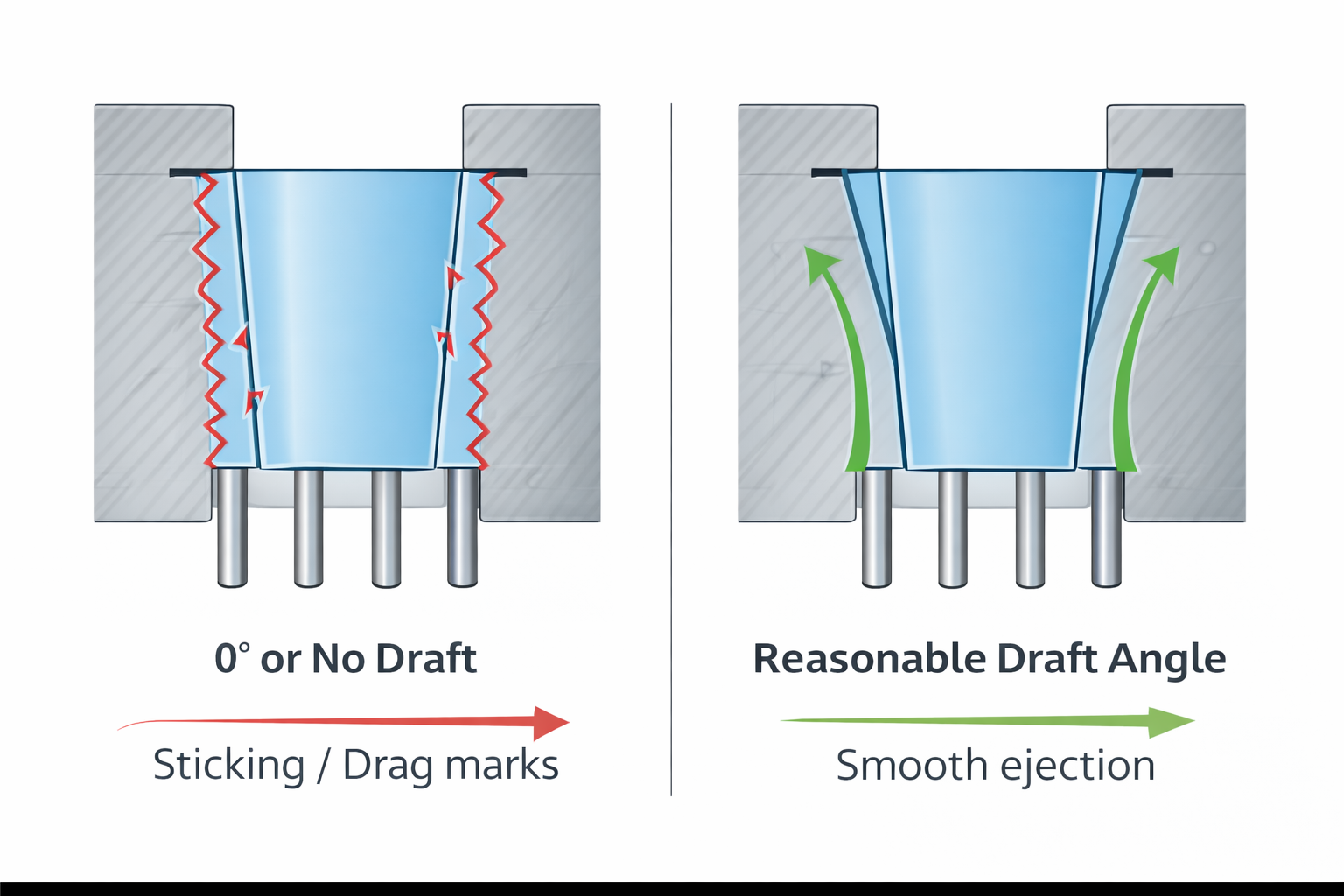
Draft angle is commonly defined as a slight taper applied to vertical walls of a plastic part to allow it to eject smoothly from the mold, a standard principle widely referenced in injection molding design guidelines.
On drawings, draft is often treated as a checkbox:
- Draft applied
- Minimum value met
- Design released
From a CAD perspective, this approach seems reasonable. Once draft exists, the requirement appears satisfied.
In real injection molding, however, draft angle is not a binary condition. It is not simply a matter of “draft or no draft.” The actual value, direction, surface condition, and interaction with material behavior all determine whether a part can release consistently over time.
A draft angle that looks acceptable on a drawing can still be marginal—or even risky—once production conditions change.
Why Draft Angle Problems Rarely Appear During Mold Trials
One of the main reasons draft angle issues are underestimated is timing.
During mold trials (T0, T1, or early sampling), production conditions are intentionally forgiving.
Typical trial conditions include:
- Slower cycle times, allowing more complete cooling
- Lower injection and packing pressure
- Manual or assisted ejection adjustments
- Close monitoring by experienced technicians
- Focus on obtaining a visually acceptable sample
Under these conditions, parts with borderline draft angles often eject without obvious problems.
This creates a false sense of security.
If the part comes out cleanly during trials, the assumption is that draft is sufficient.
What trials rarely reveal is how the part will behave:
- at higher output speeds
- under tighter cycle constraints
- with fully automatic ejection
- over tens or hundreds of thousands of cycles
The real test of draft angle is not whether it works once—it is whether it works repeatedly, without intervention, in long-term production.
What Changes When Mass Production Begins
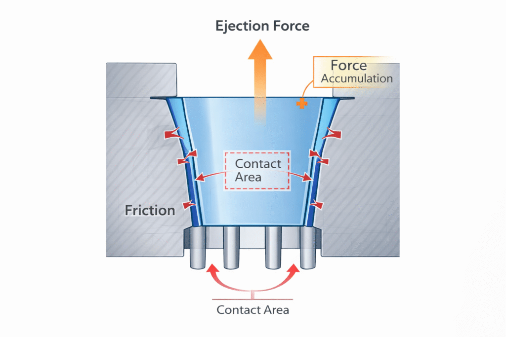
Once a project enters mass production, priorities shift. In draft angle injection molding, small design decisions often determine whether parts eject smoothly or create long-term production issues.
Production is no longer optimized for individual part quality. It is optimized for:
- Output
- Stability
- Efficiency
- Repeatability
As production ramps up:
- Cycle times are reduced
- Mold temperatures fluctuate within narrower windows
- Ejection must be fast, consistent, and fully automatic
- Small variations are amplified across large volumes
At this stage, insufficient or poorly planned draft angles begin to reveal themselves.
Common Symptoms of Insufficient Draft in Production
Draft-related problems rarely appear as a single dramatic failure. Instead, they emerge gradually. In draft angle injection molding, these issues often accumulate over time and become visible only after production has stabilized.
Common symptoms include:
Increased Ejection Force
Ejector pins must push harder to release the part, increasing stress on both the part and the mold. This often leads to pin wear, deformation, or breakage over time.
Drag Marks on Cosmetic Surfaces
Friction between the part and mold walls leaves scratches or streaks, especially on textured or matte surfaces. These marks may not appear consistently, making them difficult to control.
Texture Inconsistency Between Cavities
In multi-cavity molds, uneven ejection forces can cause visible differences in texture or gloss between parts, even when all cavities are dimensionally correct.
Sticking on Cores or Sliders
Features such as ribs, bosses, or undercuts may stick unpredictably, leading to jams, short shots, or unplanned downtime.
Accelerated Mold Wear
Increased friction during ejection wears mold surfaces faster, reducing mold life and increasing maintenance frequency.
Gradual Increase in Scrap Rate
Small ejection-related defects accumulate over time, raising scrap levels without a clear root cause.
Individually, these issues may seem manageable. Collectively, they reduce production stability and increase cost throughout the lifecycle of the project.
“Minimum Draft” vs. Production-Safe Draft
One of the most common misconceptions in injection molding is that meeting minimum draft values is enough.
Drawing standards often specify minimum draft angles—for example, 0.5° for smooth surfaces. These values are useful guidelines, but they are not guarantees of production success.
Minimum draft values do not account for:
- Material shrinkage characteristics
- Surface texture depth and pattern
- Cooling uniformity
- Part geometry and wall thickness variation
- Long-term mold wear
A draft angle that works for a smooth ABS part may fail for a glass-filled nylon component. A value that works at low volume may struggle under continuous high-speed production.
This is why experienced mold designers and manufacturing teams focus on production-safe draft—a draft angle that ensures reliable ejection even as conditions vary over time.
How Material Behavior Influences Draft Angle
Material selection plays a critical role in determining draft requirements.
For example:
- Semi-crystalline materials such as PBT or PP typically exhibit higher shrinkage, increasing friction during ejection.
- Glass-filled materials can abrade mold surfaces, increasing roughness and ejection resistance over time.
- Soft or elastomeric materials may deform during ejection, requiring additional draft to prevent sticking or distortion.
Ignoring material behavior when setting draft angles often leads to problems that only appear after production begins.
The Critical Interaction Between Draft Angle and Surface Texture
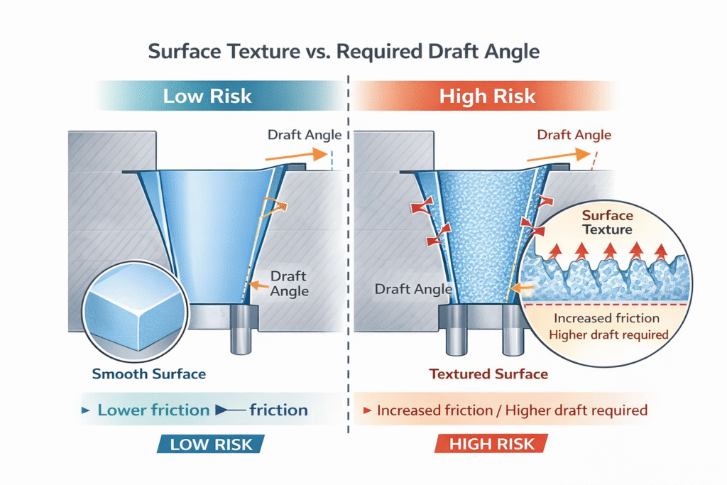
Surface texture is one of the most underestimated factors affecting draft performance.
Textures increase friction during ejection. The deeper or sharper the texture, the more draft is required to release the part cleanly.
For example:
- Fine textures may require only modest increases in draft
- Coarse or directional textures may require significantly more draft to avoid surface damage
Common texture-related issues include:
- Drag marks appearing only after extended production
- Matte surfaces highlighting minor ejection damage
- Gloss variation caused by uneven release forces
In many projects, texture decisions are finalized after draft angles have already been approved. At that point, increasing draft may require tool rework or cosmetic compromise.
Where Draft Decisions Are Often Made Too Late
Draft angle issues are rarely caused by lack of technical knowledge. More often, they are caused by timing.
Draft is frequently finalized:
- After cosmetic requirements are locked
- After texture specifications are confirmed
- After tooling design progresses
- After cost targets are fixed
Once tooling is released, options become limited. Small draft-related concerns that could have been solved early turn into ongoing production challenges.
Evaluating Draft Angle During the DFM Stage
Effective draft design is not about over-loosening geometry. It is about aligning design intent with real manufacturing behavior.
Early evaluation should include:
- Reviewing draft during DFM, not after tooling release
- Considering material shrinkage and flow direction
- Matching draft values to texture depth
- Evaluating ejection behavior, not just geometry
- Designing for repeatability rather than one-time success
This approach helps prevent predictable issues from becoming long-term production problems.
Why Draft Angle Directly Affects Cost and Lead Time
Draft angle problems rarely cause immediate failure—instead, they create slow, hidden losses over time, especially when production stability is not properly evaluated.
These include:
- Increased mold maintenance
- Additional inspection and sorting
- Longer cycle times
- Reduced mold life
- Unplanned downtime
These costs rarely appear clearly in initial quotations, but they accumulate throughout the production lifecycle and directly affect delivery reliability.
Final Thoughts
Draft angle is rarely the single reason a project fails.
But it often determines whether production remains stable—or gradually degrades over time.
From a manufacturing perspective, draft angle injection molding has a direct impact on ejection stability, cost, and long-term production reliability.
In injection molding, success is not defined by producing a good sample.
It is defined by producing consistent parts, efficiently and repeatedly, over the full life of the mold.
Small design decisions made early—such as draft angle—often decide that outcome.
In practice, draft angle injection molding is one of the most overlooked factors affecting long-term production stability.